


 |

|

|

|
|
 |
 |
|||
| Colliery Engineering | November, 1924 |
Washery and Treatment of Fines.
At the William Pit a washery of 70 tons per hour capacity, acting on the Luhring principle, and manufactured by Campbell-Binnie, Reid & Co., of Hamilton, treats the coal down to a ¼-in. screen, giving an average ash content in the washed product of 6 per cent. Undersize from the ¼-in. screen is sprayed with fresh water over screening plates perforated with 1/8-in. round holes, reducing the ash content in the material above the plates from 10 to 8 per cent., and this, when mixed with nuts, gives a coking slack containing 6½ per cent. of ash. The slurry — that is, all material falling through the 1/8-in. perforations — then contains from 35 to 37 per cent. of ash. Previously part of the slurry went in with the coking coal, whilst the greater portion went to waste. Now, however, it is led to the "H.H." concentrating table shown in Fig. 11, and a saving of some 400 tons of coal per month is effected. The concentrator, which was supplied by Hugh Wood & Co., of Newcastle-upon-Tyne, is 15 ft. in length by 7 ft. broad; it consists essentially of a sloping table fitted with longitudinal tapering riffles over which the pulp runs, admixed with a liberal supply of water. An unbalanced pulley reacting against two adjustable helical springs gives a bumping motion to the table, which, as can be discerned in Fig. 11, is connected to the wooden foundation framework by 10 flat, laminated wooden springs. As working at present the table is given 240 bumps per minute, the stroke being capable of variation from in. to 1 in. The limit of adjustment at the back is 2½ in., thus enabling the initial tilt of 4½ in., from back to front, to be increased to anything up to 7 in. The riffles run parallel with the side of the table from the feed, or motion end, curving upwards in a gradual sweep when they are within 2 or 3 ft. from the discharge end. At the feed end the riffles are somewhat over in. deep, tapering down to something like one-fourth this depth at the discharge end; it is important, however, that the proportion of the riffles should be suitably adjusted for dealing with different classes of coal, the dimensions yielding successful results in one case not being in the least calculated to give a satisfactory separation in another.
The discharge is delivered on to a de-watering screen, with a small mesh, divided into compartments according to the ash content it is desired to have in each finished product. In this instance the screen rocks with the table, but the practice is not usual.
The product above 10 mesh is excellent stuff, free of bone coal and all goes to the ovens; it makes a coke containing 7½ per cent. of ash and 1 per cent, of sulphur. In size the coal particles vary between in. and 1/8 in. diam., and without the necessity of crushing turns out a very hard foundry coke. Fines between 1/10 in. and in. are quite clean, but are left in the washed slurry for use in the boilers. At present the fines are ladled out of the settling pond by hand, but shortly will be removed by a bucket elevator. They are allowed to drain on the ground for a few days and are then sent to the boilers; as used here they contain about 15 per cent. of moisture and 15 per cent. of ash. The impurities in the slurry are chiefly fireclay with a small amount of fire pyrites; the pyrites, if not too fine, say, below 60 mesh, is discharged freely from the end of the table, but if in a very finely divided state some of it cannot he prevented from being carried over the riffles to the main body of the water and coal. Sulphur in the pulp before treatment amounts to 5 per cent., this figure being reduced to 0.86 per cent. in the grain coal for coking recovered over the 10-mesh sieve. In the boiler coal the sulphur content has not been taken, but its presence can be quite easily distinguished by the eye.
Good as are these results, it is perhaps as well to mention that a table of this type is not working to the best advantage on material of this sort, a considerable proportion of which has been reduced to powder form as a result of the abrasive action of the washer. Where minerals have to be separated hydraulically in this manner it is desirable that the crushed particles should be angular in form, since a powdery product does not obey the laws ordinarily applicable to equally falling bodies in water and a clean separation is rendered impossible. Furthermore, at Allerdale, the amount of slurry treated per hour does not amount to more than 3 tons, and as the table requires a certain minimum of water before it will operate at all effectively, the water is greatly in excess of the quantity calculated to give the best results. The slurry runs over the table with quite ten times its weight of water, whereas, if it were possible to give a full feed of coal, the relative proportions of coal and water would be as 1 to 3 or even less (1 to 1½), and a much better separation would be obtained.
Coking and Power Plant.
In close proximity to the William Pit is a compactly arranged coking plant of Koppers usual semi-direct type. The benzol, however, is absorbed by gas oil instead of creosote, with very satisfactory results. By this means the cost of production is considerably reduced, while the yields of benzol are quite as high as with creosote oil. In addition, the corrosion usually experienced with the latter is obviated. Furthermore, the gas oil being a naphthalene solvent, prevents any stoppages in the pipes and the benzol scrubbers.
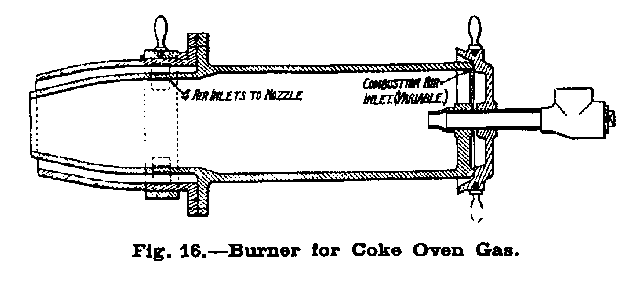
The gas from the coke ovens is consumed in a battery of four Stirling boilers, three of which suffice to raise steam for the requirements of the power plant, while the fourth is a standby. A view of the battery is given in Fig. 14; it is interesting to note that the gas burners used in this plant are a patent of Mr. F. D. Harper, manager of the coking plant. They are to be seen to the left of the battery in the figure just mentioned and a sectional drawing is reproduced in Fig. 16. A high efficiency is claimed for this burner, which is certainly accessible for inspection, robust in construction and capable of a high degree of regulation. The boilers are also fitted with Richardson's furnace for burning inferior grades of fuel. Washery slurry and coke dust are burnt equally well in this grate, which is an invention of Mr. R. Richardson, the colliery engineer at Allerdale. Both the gas burner and the furnace are manufactured by the Harper Patent Burner Co. Ltd., of Workington.
High-Tension Cable Line.
The cheapness with which electrical power can be generated with the washery slurry and coke oven gas has induced the management to electrify the plant at Buckhill by means of a high-tension cable line connecting it with the power station at the William Pit. The main unit here consists of a 530 kw. 3-phase turbo-alternator, which generates current at 500 volts. A transformer from the works of the English Electric Co. Ltd. raises the voltage to 3,000, for transmission to Buckhill, where it is again reduced to 500 volts, by a similar transformer, for use in the various motors. The low-tension connection between the switchboard and the transformer is formed by two 0.4 sq. in. 3-core cables in parallel; those on the high tension side consist of a 0.075 sq. in. 3-core cable. After leaving the power station the latter cable runs for a distance of 60 yd. to a terminal H (Fig. 18) pole and is then continued on A poles (Fig. 17). At the two points where railways are crossed H poles are again used, the cable being run under the line in a cast-iron pipe.
At the Buckhill end the incoming cable is taken from the overhead line for a distance of about 100 yd. and led to a two-cubicle switchboard supplied by Switchgear & Cowans Ltd. A 0.1 vulcanised bitumen, double wire armoured shaft cable is employed, working at 3,000 volts. The various cables were manufactured by the Macintosh Cable Co. Ltd., who also undertook the work of erecting the overhead line.
Washery Refuse Dump.
Fig. 15 gives a view of the waste heap, and shows the system of tipping the washery refuse. Although this and more or less similar systems are common enough in some localities, an illustration of the arrangement here was thought to be of sufficient interest for inclusion, in view of its simplicity and the controversy on dumping systems which has recently taken place in our columns. It may be pointed out that in this case a deep valley beyond the heap obviates the necessity of moving forward the tipping frames except at very infrequent intervals, which enables the system to work under extremely favourable conditions. The fact that the tubs are tipped by hand necessitates, of course, the constant services of workmen on the top of the heap. The tubs are of 9-cwt. capacity, and the haulage gear consists of a single drum, driven by a Siemens 30-h.p. 500-volt motor, which enables the full load to be raised as the carriage containing the empty tub is being lowered.
Drawings and Photographs accompanying the article


Article reproduced from a copy of the magazine held at National Mining Museum Scotland, Newtongrange, Midlothian.




 Contains public sector information licensed under the

