


 |

|

|

| |
 |
 |
|||

November, 1924
Notes on a Cumberland Colliery
Drawings and Photographs accompanying the article
| Sample | Description |
|---|---|
 | Fig. 1 — Plan and Section, showing Ground Traversed by Ropeway and High Tension Cable |
 | Fig. 2 — Details of Ropeway crossing Derwent Valley |
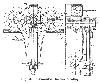 | Fig. 3 — Automatic Carrier Trolley |
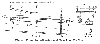 | Fig. 4 — Frame for Attaching and Detaching Trollies |
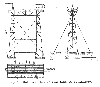 | Fig. 5 — Outline of Bridge over L.M. & S. Railway |
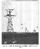 | Fig. 6 — View of Ropeway showing Type of Steel Pole |
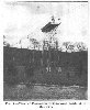 | Fig. 7 — View of Protection Bridge over L.M. & S. Railway |
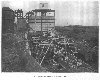 | Fig. 8 — Loading Station at Buckhill Pit |
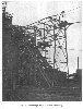 | Fig. 9 — Discharge End of Aerial Ropeway |
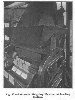 | Fig. 10 — Automatic Weighing Machine at Loading Station |
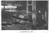 | Fig. 11 — View of Concentrating Table |
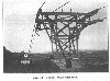 | Fig. 12 — Special Angle Standard |
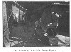 | Fig. 13 — Loading Chutes under Storage Hoppers |
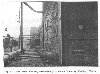 | Fig. 14 — Gas Fired Boilers, alteratively fitted for Burning Washery Slurry |
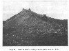 | Fig. 15 — View of Refuse Dump showing Carriers for Tubs |
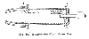 | Fig. 16 — Burner for Coke Oven Gas |
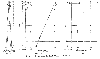 | Fig. 17 — Types of Poles used in High Tension Cable Line |
Article reproduced from a copy of the magazine held at National Mining Museum Scotland, Newtongrange, Midlothian.




 Contains public sector information licensed under the

