


 |

|

|

| |
 |
 |
|||

August, 1959
The Murton Coking Plant
Drawings and Photographs accompanying the article
| Sample | Description |
|---|---|
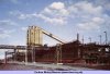 | Fig. 1. The pusher side of the oven batteries with the pusher machine and ovens coal bunker |
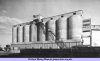 | Fig. 2. The coal blending and storage bunkers |
 | Fig. 3. The coal handling, blending and crush plant |
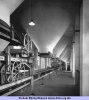 | Fig. 4. The ground floor of the blending bunkers showing the constant weight feeders and belt conveyor |
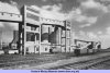 | Fig. 5. The blending bunkers with the coal conveyors from the washery |
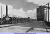 | Fig. 6. A view across the top of the oven batteries looking towards the ovens coal bunker |
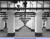 | Fig. 7. The oven basement showing the coke oven fuel gas piping |
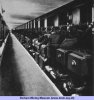 | Fig. 8. The reversing valves in the coke side alleyway |
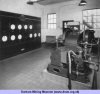 | Fig. 9. The battery control room showing the reversing machine |
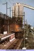 | Fig. 10. The coke side of the oven batteries |
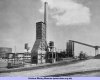 | Fig. 11. The coke quenching station with the oven batteries in the background |
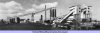 | Fig. 12. A general view of the plant from the coke screening station end |
 | Fig. 13. Flow diagram of the coke handling, screening and storage plant |
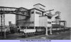 | Fig. 14. A view of the rail loading side of the coke screening plant |
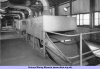 | Fig. 15. The secondary coke grading screens |
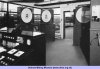 | Fig. 16. The coke weighers in the coke handling plant control room |
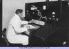 | Fig. 17. The coal handling plant control desk |
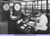 | Fig. 18. The coke handling plant control room. The 'domestic coke' boom loader can be seen outside |
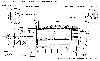 | Fig. 19. The W-D Gamma Interlock coke pushing control system |
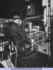 | Fig. 20. The armchair control unit on the pusher machine |
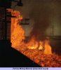 | Fig. 21. Close-up view of a coke discharge. At the top of the picture can be seen the transmitter unit of the W-D Gamma Interlock system, mounted on the coke guide |
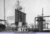 | Fig. 22. The producer gas plant showing the gas scrubber on the right |
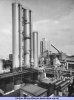 | Fig. 23. General view of the byproduct plant showing the benzole scrubbers and secondary cooler, with the electro-detarrers and primary coolers on the right and the oil/water heat exchangers in the foreground |
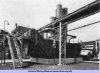 | Fig. 24. The liquor flushing and separating tank |
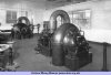 | Fig. 25. The turbine-driven gas exhausters |
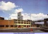 | Fig. 26. The central byproduct plant building with the byproduct and benzole recovery plants beyond |
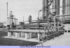 | Fig. 27. The liquor coolers and oil/water heat exchangers in front of the benzole scrubbers |
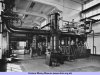 | Fig. 28. The two motor-driven gas boosters and, in the foreground, the steam-driven gas booster |
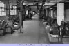 | Fig. 29. General view of the pump room showing the liquor flushing and wash oil circulating pumps, etc. |
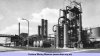 | Fig. 30. General view of the byproduct plant with the crude benzole plant in the foreground |
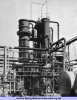 | Fig. 31. The wash oil still and vapour/oil heat exchangers |
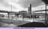 | Fig. 32. General view of the byproduct recovery plant |
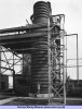 | Fig. 33. The concentrated ammonia liquor plant — the liquor still and dissociator |
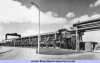 | Fig. 34. The box-tray type oxide purifiers |
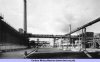 | Fig. 35. The pusher side of the oven batteries and the central byproduct plant building |
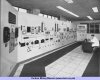 | Fig. 36. The byproduct and benzole plants control panel with the annunciator board on the left |
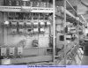 | Fig. 37. The back of the byproduct and benzole plants control panel |
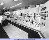 | Fig. 38. The byproduct and benzole plants control panel with the budgetary control board on the right |




 Contains public sector information licensed under the

