


 |

|

|

| |
 |
 |
|||

June, 1959
The Cwm coking plant
Drawings and Photographs accompanying the article
| Sample | Description |
|---|---|
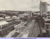 | Fig. 10. A general view of the byproduct plant |
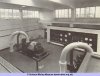 | Fig. 11. The exhuaster house |
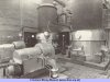 | Fig. 12. The two Krauss Maffei continuous centrifuges and the evaporators in the sulphate of ammonia plant |
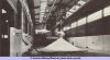 | Fig. 13. The sulphate of ammonia store with pneumatic handling pipeline and branches of the left |
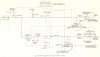 | Fig. 14. Flow diagram of the gas control system |
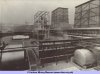 | Fig. 15. The benzole recovery plant |
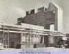 | Fig. 16. The power station, with the turbine house in the left foreground and behind it the boiler house |
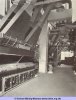 | Fig. 17. The three tri-drum boiler units in the power station |
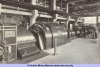 | Fig. 18. The two G.E.C. double pass-out turbo-alternators in the power station |




 Contains public sector information licensed under the

