


 |

|

|

| |
 |
 |
|||

May, 1959
The Cwm coking plant
Drawings and Photographs accompanying the article
| Sample | Description |
|---|---|
 | Cwm coking plant |
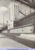 | Fig. 1. The ram side of the coke-oven plant which has 108 ovens and a 3,000 ton service bunker |
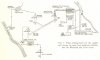 | Fig. 2. Final arrangements for the supply and storage of water from adjacent collieries and the Rhondda and Cwm rivers |
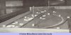 | Fig. 3. The sand model used for site planning |
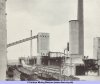 | Fig. 4. Coke side of the coke-oven battery showing the coke quenching station in the foreground |
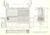 | Fig. 5. Detail sections through the ovens. Provision is made for possible future lean gas firing |
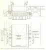 | Fig. 6. The magnetic alignment system which ensures that ram and coke guide are correctly positioned |
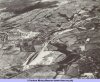 | Fig. 7. Aerial view of the Cwm site before constructing of plant |
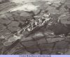 | Fig. 8. Aerial view from a similar angle after completion of the installation |
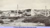 | Fig. 9. General view of Cwm coke works; the power station is on the extreme left |




 Contains public sector information licensed under the

