


Mail: Webmaster

|

|

|

|
|
Chapter III
REPAIRING A BROKEN BELT
A Top Belt
 1. Locate the break.
2. Slacken off the Tension End by releasing the Sylvesters.
3. Pull the two ends into a suitable place to work.
4. Get all the tools required for repairing the belt to the place.
5. Prepare the belt ends as shown in Chapter II, Section A, page 26
6. Fix and fasten the couplings to each belt end as shown in Chapter II, Section B, page 27, making sure that the two ends mate.
7. Place the belt back on the structure.
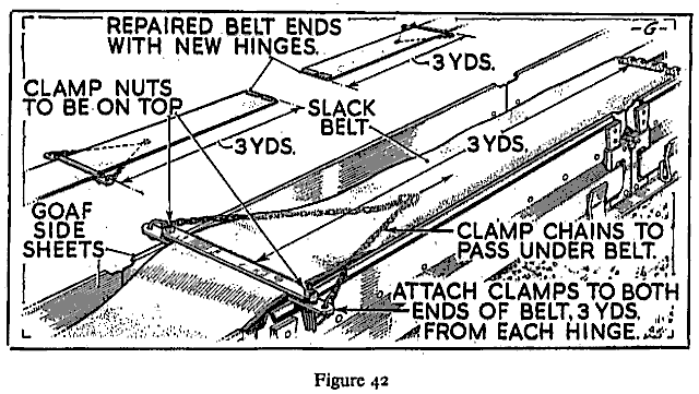
8. Attach clamps securely to both ends of the belt, about three yards from each coupling, with clamp nuts on top (Figure 42).
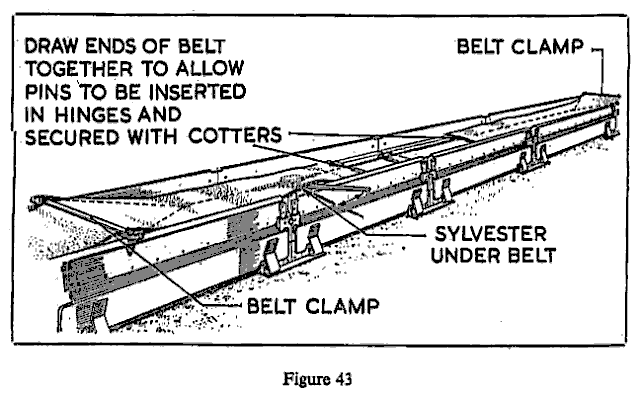
9. Beneath the belt attach sylvester chain to one clamp and the sylvester to the other clamp. Operate the sylvester and draw the ends of the belt together until the coupling pins can be inserted. (Figure 43).
10. Insert coupling pins (secure where necessary with cotters), then remove the sylvester and clamps. Trim the four corners at the joint.
11. Tension the belt by pulling back the tension end with the sylvester.
12. Centralize the belt on the intermediate structure and on the return drum.
B Bottom Belt
1. Locate the break.
2. Uncouple the top belt at the nearest point to the break and roll back on the intermediate structure, clear of both broken ends.
3. Slacken off Sylvesters at tension end.
4. Remove the intermediate structure to expose both broken ends of the belt.
5. Prepare the broken ends as shown in Chapter II, Section A, page 26.
6. Fit and fasten the couplings to both ends as shown in Chapter II, Section B.
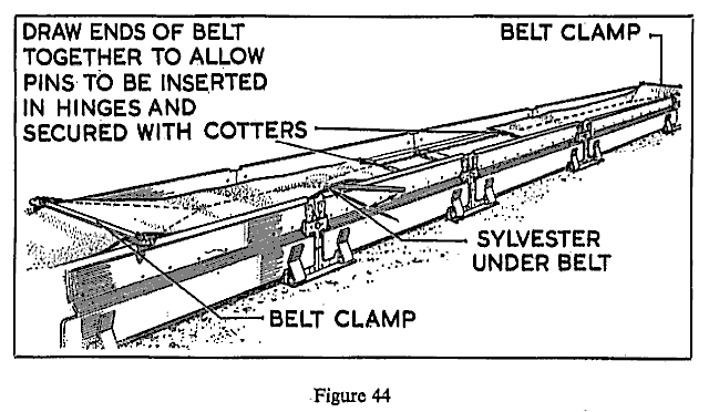
7. Attach sylvester and clamps (Figure 44), and draw the belt ends together.
8. Insert coupling pins (secure where necessary with cotters), then remove the sylvester and clamps.
9. Replace intermediate structure in original position.
10. Unroll the top belt back on to the intermediate structure.
11. Attach clamps to the top belt, three yards from each hinge.
12. Beneath the belt attach sylvester chain to one clamp and the sylvester to the other clamp. Operate the sylvester and draw the ends of the belt together until the coupling pins can be inserted. (Figure 44).
13. Insert the coupling pins (where necessary secure with cotters).
14. Remove the sylvesters and clamps.
15. Tension the belt by operating sylvesters at the tension end.
16. Centralize the belt on the intermediate structure and on the return drum.
C Broken Belt in Engine End or Tension End
1. Slacken off sylvesters at tension end.
2. Pull both broken ends away from the structure of drive head or tension end into a suitable place where ends can be prepared.
3. Prepare the ends as described in Chapter II, Section A, page 26.
4. Fix the fasteners to both ends of the broken belt as described in Chapter II, Section B, page 27.
5. Uncouple the top belt at the joint nearest to the break.
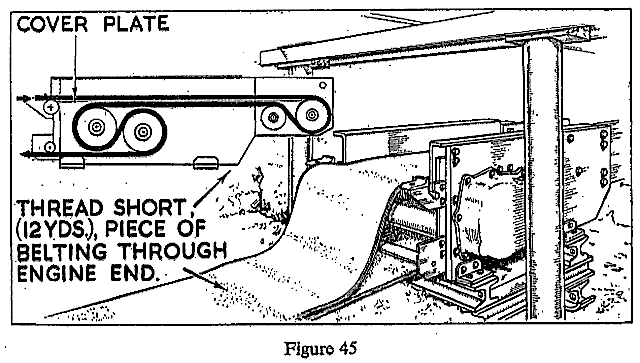
6. Thread this uncoupled piece round the driving drum or return drum (Figure 45).
7. Couple to the bottom belt.
8. Fix clamps 3 yards from each loose end of the belt, fix sylvester and draw the ends together as shown previously in Figure 44.
9. Couple the belt ends together.
10. Remove sylvester clamps.
11. Tension the belt by operating the sylvesters at the tension end.
12. Centralise the belt on the engine and on the return drum.
Note: Where Bristol couplings are used for belt jointing the belt ends must be drawn together before the joint can be made. Care must be taken that one of the ends does not get turned over or passed round props whilst they are being drawn together.


Back |

Home |
Copyright © 1999-2012 by The Durham Mining Museum and its contributors
Page last updated: 01 Jan 2008 |

Search |

|