


|

|

|

|
|
 |
 |
|||
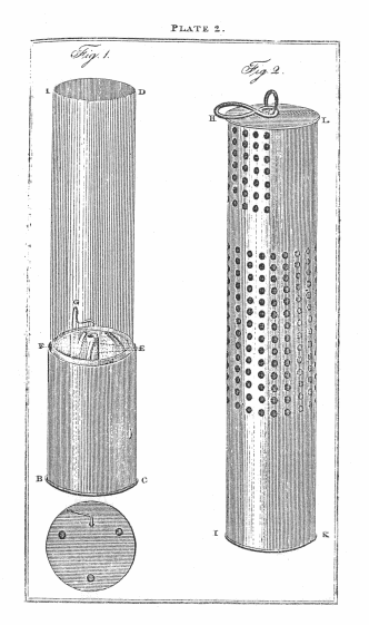
A. B. C. D. the lamp.
E. Three small tubes passing through the oil vessel, and
out at bottom B.C. to admit the air to the flame.
F. the tube for the wick.
G. a small wire to raise and trim the wick.
H. I. K. L. the cover to protect the glass cylinder.
M. the bottom of the lamp shewing the three apertures, and the wire to trim the wick.
This was ordered immediately after the former one had been tried ; and, on the 4th of November, was exposed to a blower in the same mine. — it was found to burn considerably better, and to be perfectly safe ; but as it did not entirely answer my expectations, I determined to surround the oil vessel with a number of capillary tubes, as shewn ny the section, fig. 3, plate 3, in which the case apertures would present the same appearance as the perforations in fig. 1, in the same plate ; but I thought that the air would have an easier access, and that the effect might be the same if I cut away the middle of the tubes; and that the flame, if it passed through the apertures at the top would not communicate the explosion to the hydrogen beyond the plate below. I constructed a Lamp upon this principle, and found that the holes having been punched very small, the flame never passed even through the first plate.





 Contains public sector information licensed under the

