


|

|

|

|
|
 |
 |
|||
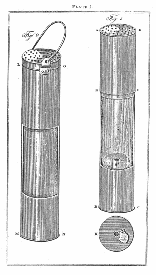
A. B. C. D. the lamp made of tin.
G. the glass cylinder.
A. E. F. D. the top which takes off to admit the glass cylinder,
and keeps it tight to the bottom B.C.
H. two tin tubes, the cavity between them for the wick ; the
interior one to admit the air.
I. the chamber for the oil.
K. The bottom of the lamp with the slide P. to regulate the quantity of air to be admitted.
L. M. N. O. the case in which the lamp is carried, with the tin back (which in fig. 1. is seen through the glass at G.) turned towards the opening where the light is not required.
This Lamp was tried in Killingworth Colliery, on the 21st of October, 1815. The idea I had long entertained, and the drawing was shewn to several persons employed in that concern, two months before the day above mentioned, when, I carried it with safety into a part of the mine where a strong blower of hydrogen was coming off. An experiment which was immediately repeated in the presence of two persons employed in that concern.





 Contains public sector information licensed under the

