


|

|

|

|
|
 |
 |
 |
||
VI — Investigation Of The Overwind
Investigation before Normal Winding was resumed
30. The investigation of the overwind by officials of the National Coal Board and H.M. Inspectors of Mines in the North Eastern Division commenced about two hours after the overwind and it continued until the morning of 6th March, 1958, by which time the automatic contrivance had been modified and tested with satisfactory results.
31. The overwound ascending cage was held in the headframe by a safety catch under one end of the middle deck and by another catch under the opposite end of the bottom deck (see Drawing). The catches were not in proper working order because they had not been properly maintained. Consequently nine of the catches in one set and 11 in the other set had not returned to their operative positions after they had been pushed back by the ascending cage. In addition, four catches of the first set and one catch of the other set had only partially returned to those positions. Ineffective operation of many of the safety catches had caused the falling cage to tilt before it was finally arrested by the aforesaid two catches, which were not directly opposite. As a result of the tilting, one of the frames containing a set of catches was bent outwards about 4 5/16 inches. When the cage was examined it was found to have sustained damage to the hoop of its middle deck, which was repaired before the cage was used again.
32. The capping of the overlap winding rope was lying on the ground just in front of the winding engine house. It had made a hole in the concrete ramp to the basement and demolished some railings. The rope had been damaged in the vicinity of the capping, and consequently 25 feet of the rope had to be cut off before it was recapped and used again. It was found that the winding drum had rotated about 1.33 revolutions after it should have stopped and that about an additional 73 feet of the overlap rope had been coiled on to the drum.
33. The winding engine was examined by the investigators who found that the supply of electric power thereto was cut off, the brake solenoid was in the "Brakes On" position, and the overwind switch was open on the over-rope side of the automatic contrivance, a type C Lilly Controller. These circumstances indicated that the automatic contrivance had operated so as to cut off the supply of power and to apply the brake.
34. When the overwind occurred the winding engine was being operated by Mr. J. Mozley, aged 63 years, who came to work just before 5.30 a.m. and relieved Mr. H. Leadbeater who had operated the engine during the night shift. Mr. Mozley had not been to bed that night on account of his wife's illness and he was very upset by the accident. He said that he felt there was a large unbalanced load on the engine at the start of the wind, which proceeded normally, however, until the drum was about nine revolutions from the end of the wind, when he moved his control lever towards the "Off" or reverse position, so as to apply regenerative braking. This action apparently did not reduce the speed of the engine, so he moved the lever progressively into the full reverse position, but even this had no noticeable effect on the speed of the drum. By this time, the drum was only about five revolutions from the end of the wind, so he moved the brake lever into the "On" position, and kept the power control lever in the full reverse position. The two relief winding enginemen, who were in the engine house at that time, heard the screech of the brakes which eventually brought the drum to rest about one and one third revolutions past the position at which it was normally stopped.
35. Mr. Mozley said that the man-safety lever was in the correct position to set the Lilly Controller for carrying persons, which was confirmed by several witnesses, and that the overspeed switch and the overwind switch on the Controller did not trip the safety circuit as he expected. He also said that some 15 minutes after the overwind he pressed the emergency push button which tripped the safety circuit, because he heard a thud on the brake handle that was caused by the falling brake solenoid.
36. Mr. Mozley's statement about the loss of regenerative braking and the failure of the Lilly Controller to operate caused such grave concern that it was decided to make exhaustive examinations and static tests of the winding engine and the Controller with its ancillary apparatus both mechanical and electrical. No fault was found in the electrical apparatus which could prevent the Controller from functioning correctly. Likewise no fault was found in the mechanical apparatus which could result in the loss of braking effort or which could prevent the Controller from functioning correctly. For example, when the overspeed or overwind switches were opened by the action of the speed governor or the overwind limit cam respectively. These tests also showed at an early stage of the investigation that the backing out switches were in the open position. Lubricating oil from the mechanism of the Controller was found to have run down the vertical conduit containing the electrical wiring connected to the Controller. Although tests of the wiring in situ did not reveal any defect the wiring was renewed. The old wiring was specially examined after it had been removed and it was found to be free from any defect that could prevent the Controller from functioning correctly.
37. In view of the satisfactory results of the above static tests, the winding apparatus was made ready for a series of landing speed tests, in which the Lilly Controller or automatic contrivance was fully engaged for carrying persons. These tests established beyond any doubt that :—
| (a) |
The winding engine drum attained a speed of about 68 r.p.m. when the ascending cage was empty and the descending cage contained a load equivalent to the maximum number of men allowed in it at any one time. This speed is equivalent to a rope speed of 63 feet per second when the rope is coiling on the large diameter of the drum.
| |
| (b) |
The descending cage eventually passed the artificial landing, used for the purpose of the test, at a speed of about 19 feet per second despite the operation of the Lilly Controller, which functioned correctly.
|
38. The tests showed quite clearly that the winding apparatus should not be used again for carrying persons until the automatic contrivance on the winding engine had been modified to satisfy the requirements of Regulation 7 of the Coal and Other Mines (Shafts, Outlets and Roads) Regulations. 1956.
39. The automatic contrivance was fitted, therefore, with a Man-Safety Tappet, so constructed and adjusted as to prevent the cage from travelling at a speed greater than 40 feet per second when it was carrying persons. Subsequent tests of the automatic contrivance indicated that it prevented the cage from passing the artificial landing at a speed exceeding 5 feet per second and that it was able to satisfy the requirements of the Regulation. All the representatives agreed, therefore, that the winding apparatus could be used again for normal winding which started at 2 p.m. on 6th March, 1958.
Investigation after Normal Winding was resumed
Brakes
40. An examination of the arrangement, construction and operation of the Lilly Controller, ancillary apparatus and the brake engine indicated to the Area Chief Engineer that in certain circumstances there might be undue delay in the application of the mechanical brakes. Consequently on 16th March a series of tests was made to determine the performance of the brake engine when the brakes were applied by the winding engineman's brake lever, the Lilly Controller or the combined action of the lever and the Controller. The results of these tests are shown in Table I and in the Chart.
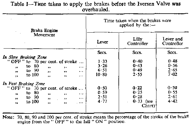
41. On 17th and 18th March, I examined the brake engine and the detailed drawings thereof, considered the results of the tests shown in Table I and came to the conclusion that the Iversen Valve was neither set correctly nor working properly. The management readily accepted my suggestion that they should alter the Valve setting and arrange for representatives of the Fraser and Chalmers Engineering Company, a subsidiary of the General Electric Company, Limited, to make a thorough examination of the Valve as soon as possible. The examination was made on the night of 20th March, when it was found that the sleeve inside the valve box was so tight that it could only be moved by force whereas it should have worked quite freely. After the sleeve had been thoroughly cleaned, eased and put back to work the Iversen Valve functioned properly. The performance of the brake engine was then determined by another series of tests of which the results are shown in Table II and in the Chart.
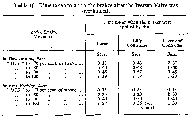
42. The information in Tables I and II and in the Chart shows that, both in the "Slow Braking" and the "Fast Braking" Zones, the defective Iversen Valve caused an alarming delay when the brake was applied by the engineman's brake lever or by the combined action of that lever and the Lilly Controller. It also shows that prior application of the brake by the brake lever prevented the Controller from applying the brake anything like so quickly as it would have done otherwise. This was caused, firstly, by the defective Iversen Valve which did not allow the compressed air to exhaust as rapidly as it should have done and, secondly, by the linkage used for operating the brake engine by means of the brake lever, the fast and slow braking device and the emergency solenoid which was controlled by the Controller and associated safety devices. This linkage incorporated a slotted link, shown in Plates I, II and III, by which the solenoid was reset after the Controller had operated. As a result of this arrangement, prior application of the brake by the engineman's brake lever prevented the solenoid from falling more than about half an inch instead of the two inches that it would have fallen otherwise. Consequently the solenoid could not open the air escape valve on the brake engine cylinder in the fast braking zone and thus the time of application of the brake in that zone was dependent on the speed at which the air was exhausted through the defective Iversen Valve, which caused a perilously long delay.
Lilly Controller
43. The Duplex head on the Controller, i.e. a head with two governors. was fitted by the Metropolitan-Vickers Electrical Company, Limited, in July, 1953. Examination of the sheet of data Which the former Area Chief Engineer of the National Coal Board forwarded to that Company When the Duplex head was ordered showed that the normal winding speed was declared as 49.2 feet per second and that the Company was not asked to provide for a reduced maximum speed for man winding. In other words the Company was not asked to provide a Man-Safety Tappet.
44. The Controller is designed to prevent the winding engine from travelling at an excessive speed and to enforce a progressive reduction in speed as the cages approach the ends of the wind. The reduction of speed is effected by two deceleration or retardation cams. One cam controls the last four and one quarter revolutions of the winding drum when the overlap-rope cage is descending, which is equivalent to the last 149 feet of travel of the cage. The other cam controls the last four revolutions of the winding drum when the underlap-rope cage is descending, which is equivalent to the last 140 feet of travel of that cage. This means that the winding engine may be accelerated until it attains a speed just less than that permitted by the Controller and that it may run at that speed until the descending underlap-rope cage is nearly 140 feet from the end of the wind.
45. The accelerating solenoids are fitted to the Controller so that during the early part of a wind the winding engine may be accelerated at a greater rate than the minimum rate that it must be decelerated towards the end of a wind. This is achieved by interfering with the normal effect of the appropriate deceleration cam on the Controller during the accelerating period only. Unfortunately, however, some overwinds have occurred on a very small number of winding engines as a result of defects in the accelerating solenoids Which caused them to function incorrectly during the decelerating period. In view of these dangerous occurrences, the accelerating solenoids on the Controller of this winding engine were specially examined and found to be in proper working order.
46. Between July, 1953 and October. 1955, periodic tests of the operation of the Lilly Controller were made under the direction of the Area Chief Engineer's Department. These tests involved the application of power to the winding engine when, as required by the Regulations, attempts were made to land the descending cage at an excessive speed. The results of the tests indicated to the management that the cage could not be landed at the pit bottom at a speed exceeding 5 feet per second and that the maximum speed of winding either men or minerals was 57 feet per second; this speed was 16 per cent. higher than the speed declared by the management when they ordered the Duplex head for the Controller. But Mr. Leadbeater, one of the winding enginemen, said that he had lowered materials at a speed of 60 feet per second without being stopped by the Controller. Therefore the maximum speed of winding was probably higher than 57 feet per second, a condition which had not been revealed by the method of testing.
47. Between October, 1955, and the time of the overwind, periodic tests were made without the application of power and thus they were not nearly so thorough as formerly. This method of testing without power was adopted because the Area Chief Engineer was concerned about a crack in one of the cast iron scrolls of the winding drum and he thought that it would not be wise to continue to use the previous method of testing which might have an adverse effect on the crack. He was convinced, however, that the results of the tests indicated that the performance of the automatic contrivance was such as to satisfy the statutory requirements.
48. In addition to the above tests, the operation of the Lilly Controller was tested every night by the winding engineman on duty. Such a test was made on the night immediately prior to the overwind when Mr. Leadbeater reported in the winding engineman's daily log book that he had tested the overwind switches, the emergency push button, the man-riding signals and the emergency stop signals and that he found them in order.
Brake Contactor
49. It came to light that Mr. E. Williams, assistant mine electrical engineer, went into the engine house about ten minutes after the overwind and asked the two relief enginemen, the engineman who was going off duty and Mr. Mozley what had happened and Why the latter had not used the emergency push button. When Mr. Mozley said he had not thought about using the push button, Mr. Williams opened the right hand side door of the contactor cubicle where he saw that the brake contactor was closed. He re-closed the door without noticing whether any other contactor was closed and returned to the electricians' shop without telling anyone of his discovery. A few minutes later he sent an electrician to instruct the winding enginemen that they should not touch anything. Shortly afterwards one of these men came to the shop and said that Mr. Mozley wanted to see him. He returned to the engine house where Mr. Mozley said that before the above instruction was received he had operated the emergency push button and had heard the contactor drop out. Mr. Williams then said to him "I could not understand why that contactor was closed ". He again opened the door of the contactor cubicle and found that the brake contactor was now open.
50. Although the evidence on the reporting of the above situation is somewhat conflicting and disturbing, it would appear that some of the senior engineers and H.M. inspectors of Mines were not told that Mr. Williams bud found the brake contactor closed until after the winding engine had been put back to work. My investigations and the replies to my questions showed that the brake contactor might have been found closed by Mr. Williams after the overwind as a result of any of the following circumstances :—
| (1) |
Failure of the Lilly Controller owing to electrical or mechanical defects or incorrect adjustment.
| |
| (2) |
Failure of the brake contactor.
| |
| (3) |
Resetting of the safety equipment after the overwind in the manner described in paragraph 23.
|
51. Unfortunately no investigation was made as it should have been immediately after Mr. Williams had looked inside the contactor cubicle, the four winding enginemen were not instructed immediately that they must leave everything undisturbed and Mr. Mozley's action in pressing the emergency push button seriously interfered with the subsequent investigations. Nevertheless the exhaustive examinations and tests that were made did not reveal any defect or incorrect adjustment that could cause either the Controller or the contactor to fail. Moreover all the conditions and the evidence, except that of Mr. Mozley and Mr. Williams, indicated that the Controller and the contactor did not fail and that they had never failed.
Regenerative Braking
52. In view of Mr. Mozley's statement that his attempt to apply regenerative braking immediately prior to the overwind did not result in the speed of the drum being reduced, the Area Chief Engineer conducted some tests on regenerative braking which were witnessed by representatives of the General Electric Company, Limited. These tests showed that the regeneration obtained for various movements of the power lever from the full speed forward position towards the full speed reverse position were substantially the same as those measured when the winding engine was commissioned some 16 years ago. Nevertheless the regeneration obtained when the power lever was moved from the full speed forward position to the full speed reverse position was only 70 per cent. of the full load and it was very much less than that obtained when the lever was moved to only the 60 per cent. full speed reverse position. In other words much less regeneration was obtained when the lever was in the full reverse position, into which it was put by the winding engineman immediately prior to the overwind.
53. Three of the winding enginemen commented on regenerative braking: Mr. Anderson said that it didn't always come the same and that on odd occasions it seemed to take longer to act: Mr. Leadbeater said he had been troubled occasionally by losing power in reverse; and Mr. Johnson said that sometimes when a heavy load was going down and the engine was going fast regenerative braking does not occur. The last statement is very significant, because when the overwind occurred there was a heavy load going down, the engine was going fast and Mr. Mozley said that he seemed to lose reverse power. Mr. S. Luxmore, H.M. Electrical Inspector of Mines, observed that at speeds in excess of 50 feet per second when the engineman's control lever was moved into the full reverse position, regenerative braking far from being increased was in fact reduced.





 Contains public sector information licensed under the

