


|

|

|

|
|
 |
 |
|||
DESCRIPTION OF THE SHAFT AND ITS FITTINGS.
Medomsley Colliery is situate about two miles north of Consett, and is owned by Messrs. the Consett Iron Company, Limited. It includes a downcast shaft known as the Busty Shaft, and it was in this shaft that eight persons lost their lives on 24th February last, when being drawn tip in the cage which runs in the northern half of that shaft. This shaft is 453 feet in depth measured from the surface level to the flat sheets at the Brockwell Seam landing ("hanging-on"), and is 10 feet in diameter within the lining. The lining is of fireclay lumps, and except for five lengths measuring in all some 98 feet is continuous throughout.
There are openings from the shaft at 114 feet and 365 feet from the surface level into the Main Coal and Busty Seams respectively, but at the time of the accident persons and coal were wound from the "hanging-on" at the Brockwell Seam only.
Two cages run in the shaft, and to keep them in their proper vertical alignment guides formed of steel rails in 18 feet lengths and weighing 41 pounds per yard were provided and disposed in the manner shown in plan in Figure 1.
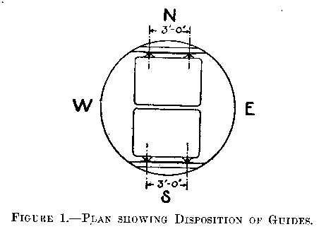
The original guides were installed some 20 years ago and continued to be in regular use until January, 1921, when a part of the North-West guide, the bulb having become severely worn, was renewed from the shaft bottom to 70 feet above the point, known in mining parlance as "meetings" where the cages pass each other in the shaft.
Although wide inquiry was made by the colliery company, rails of exactly the same section as that of the original guides were not obtainable, but rails of as nearly similar section as could be got were put in and the bulb of the original section was tapered down to make a fine joint with the bulb of the newer section.
The guides were fixed to pitch pine buntons measuring 10 inches deep by 3 inches wide, except at the joints of the guide-rails where they were 4 inches wide, and fixed 6 feet apart vertically. Upon each bunton a steel sleeper was bolted and to these sleepers the guides were attached by bolts as shown in Figure 2. The joints between each 18 feet length of rail were made as shown in Figure 3.
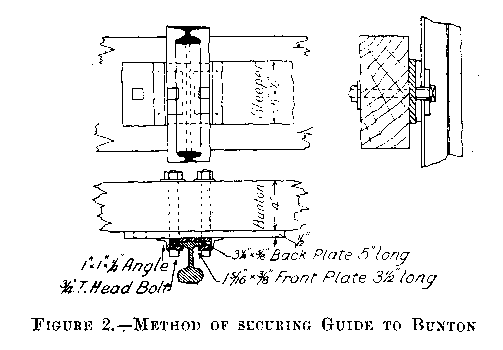
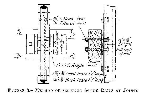
The buntons were supported by being placed in recesses in the shaft lining and then wedged tightly in position. Some were built in solid with masonry.
In addition to the wooden buntons supporting the guides there were in the shaft at the East side, at right angles to the line of pitch pine buntons, two cast iron girders, which at one time had been in use for supporting a column of pipes; also some steel rails supporting a five-inch diameter range of pipes for carrying water to the underground stables. On the West side there were wooden buntons to support electric cables and wooden boxes in which haulage ropes used to run. The wooden boxes enclosing the present haulage ropes were behind the buntons on the North side of the shaft.
The buntons, girders, rails and boxes are shown in the section of the shaft — Plate I — one of the girders, it will be seen, being about 80 feet and the other 158 feet from the surface.
Between the eastern end of the North cage and the top and bottom of the upper girder, there were clearances of 4½ inches and 5 1/16 inches respectively, this girder being in section at this point as shown in Figure 4.
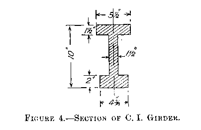
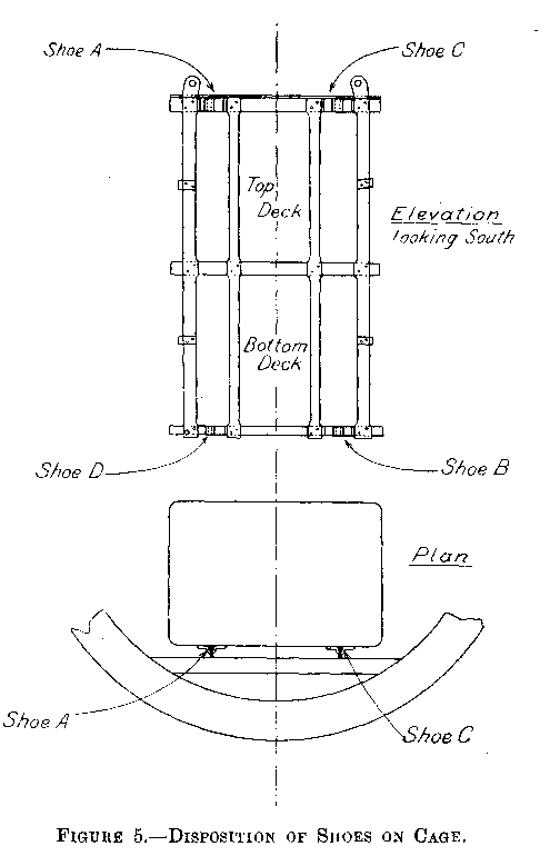
To each of the cages four shoes of cast steel were bolted, each shoe by two ¾-inch bolts, each bolt having a single nut, and the back of the shoes was recessed to a depth of 3/8 inch, but not machined, to fit on to the hoops of the cage. The disposition of the shoes on the cage is shown in Figure 5, which also shows that the cage had two decks, each capable of holding one tub. When empty the cage and chains weighed 25½ hundredweights.





 Contains public sector information licensed under the

