|
|
| The Beginning. | Description of Colliery. | The New South. | The Explosion. | The Investigation. | Cause of Explosion. | Recommendations. | Acknowledgements. | Names of Injured. | Plates. |
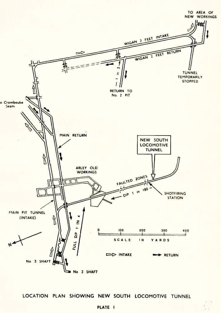
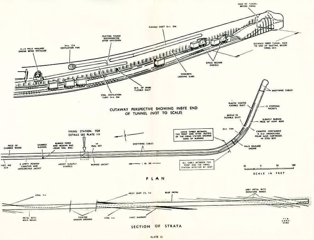
Golborne Colliery, Lancashire, on 7th. December 1957.I'm indebted to Joe Stocks for sending me this Report.INTRODUCTORY.Management.Ventilation and Safety Lamps.Development of the Colliery.II. THE NEW SOUTH LOCOMOTIVE TUNNEL.General.Support.Ventilation.Shot firing and excavation of ground.III. THE EXPLOSION.IV. INVESTIGATIONS AFTER THE EXPLOSION.
Percentage Methane.
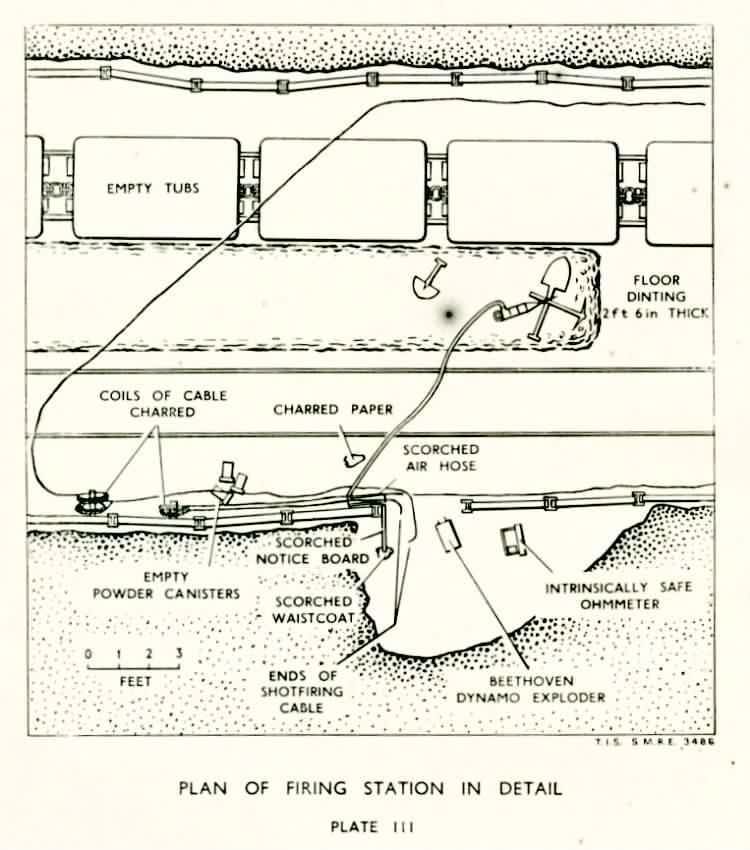
The return tubes ended 47 yards from the face of the tunnel and the firing station was 223 yards away. Although no measurements of the thickness of the layer of gas were made, the percentages suggest that there was a thin layer near the roof at the face of the tunnel, that the layer began to increase about 70 yards outbye, reached a peak 150 yards outbye and then diminished fairly rapidly. About eight hours after the fan had been stopped, an inspection by Messrs. Benson and Dobson, H.M. Senior District Inspectors of Mines and Quarries, showed that an extinctive atmosphere of firedamp and air extended from the tunnel face outbye to the firing station; the thickness of the layer was 30 inches at the face, decreasing gradually to 6 inches at the firing station. This pattern of the presence of gas was confirmed by Mr. L. Beck, H.M. Inspector of Mines and Quarries, who inspected on the next shift. After the fan had been standing about 24 hours, the greatest concentration of gas was again found in the length of tunnel between the open end of the return tubes and the face, where the extinctive layer was at least 4 feet thick. Outbye of the open end of the tubes the extinctive layer tapered evenly, as far as could be estimated, from a thickness of 2 feet at the end of the tubes to 1 foot at the firing station. There was no peak at 150 yards from the tunnel face as was suggested by the samples taken by the rescue men soon after the explosion. The same afternoon, i.e., on Sunday, 8th. December, a measurement of the air passing into the inbye end of the steel return tubes was made by Mr. Dobson, H.M. Senior District inspector of Mines and Quarries, and Mr. Albert Allan, colliery ventilation officer; a figure of 2,512 cubic feet per minute was obtained. At the discharge end of the tubes in the return the quantity was 8,200; it was observed that a number of a certain type of joints in the tubes near the air crossing (where the suction would be considerable) were leaking badly and that air was drawing inwards. A steel flap, or regulator, in the 3 feet return tubes near the air crossing was found to be in its correct position of fully open. A detailed examination of the shot firing apparatus and its cables was made by Mr. E. J. Platts, H.M. Electrical inspector of Mines and Quarries. The exploder was found on the floor with the charging handle inserted. A length of old insulated detonator lead about 6 inches long was attached to one of the terminals and a 15 inch length of similar wire was found attached to the prepared end of the core of one of the two shot firing cables. It was apparent that the two short lengths of old detonator lead had been used to facilitate connection between the exploder and the ends of the two armoured shot firing cables. Close observation of these short pieces of detonator leads showed that it appeared unlikely that they could have made electrical contact with the armouring of the firing cables when the shot was fired. Just outbye the firing station excess shot firing cable was coiled up and hung at the side of the roadway, but nearer the face the two shot firing cables were laid out on opposite sides of the roadway. The cable on the right hand side facing inbye was found to have two taped up joints in its length and there was another place where the conductor was joined together but was not taped up and was thus left exposed; the armour wires at this joint were roughly twisted together, were separated from the conductor and were well clear of both the roadway sides and its supports. This cable was suspended from the sides of the roadway at heights up to 7 feet from the floor near the firing station but lay on the floor for the last 20 yards or so near the face. When tested the cable showed good insulation resistance between conductor and armour wires. The cable on the left hand side of the roadway was suspended about 9 feet from the floor near the firing station, where it appeared to be in good condition, but much of it lay on the floor further inbye. There were six taped up joints in the run of the cable; the armour wires were not continuous electrically at two of these joints, whilst at two other places joints in the conductor had been made but had not been taped. When the cable was tested with a 500 volt insulation tester after the breaks in the armouring had been bridged, a resistance between conductor and armouring of 80,000 to 90,000 ohms was indicated; after several such tests had been made over a period of some minutes the insulation resistance broke down to zero. At the tunnel face the ends of the cables had been prepared by turning back the armour wires and binding them to the outside of the cable with old detonator wire, leaving some 1½ inches of insulated conductor exposed. When the round of shots had exploded the ends of both cables had been thrown back into the roadway. Careful examination of the tunnel (supplemented by a study of certain samples taken by members of the Flame Section of the Safety in Mines Research Establishment later) showed that the length of roadway visibly seen to have been traversed by flame was of the order of 263 yards, starting from a point 44 yards outbye of the tunnel face, the most pronounced effects being near the firing station, 223 yards from the face. Microscopical examination of certain specimens showed that there had been weak flame right up to the last arch nearest to the face. In addition to the effects already mentioned there were few plain indications of the effect of flame, the chief of these being the charring of certain random pieces of wood, the burning of scattered pieces of paper and a slight singeing of some of the canvas ducting (see Plate 11). The signs of burning were thus far from extensive and there was no evidence at all of blast in the tunnel. At the time of the explosion, three doors leading into a locomotive garage direct from the return had been blown open by pressure presumably transmitted through the return tubes. There were no indications that coal dust had taken part in the explosion, as indeed was to be expected since practically all the work carried out in the tunnel had been connected with material other than coal and no coal dust was present. Considerable trouble was experienced later in moving the gas which was present some distance back from the tunnel face; it was found necessary to install three forcing fans near the entrance to the tunnel, delivering at different points along the length of the tunnel. An interesting observation was that some of the air from the two furthest outbye deliveries returned back along the body of the tunnel to the air crossing, a natural result of the inability of the return tubes to carry the amount of air then being supplied. Contents V. THE CAUSE OF THE EXPLOSION.The source of the firedamp.Evidence of the presence of gas in workings after an explosion is not generally regarded as altogether indicative of the conditions before the explosion on account of the effects of the pressure and later the suction produced by the explosion itself. I believe, however, in a case such as this where no area of waste was involved and the excavated area contained no crevices and bed separation cavities, this principle does not apply so fully: the extent of the gas as found after the explosion may therefore be taken as a useful guide as to what was present before. It will be remembered that the samples taken by the rescue men at the crown of the steel arch supports immediately after the fan had been stopped showed that the greatest percentage of gas, 33 per cent., was present 150 yards from the face of the tunnel, that the percentage fell as the face was approached and inbye from the end of the return tubes the percentage was more or less constant at about 2 per cent. After an interval of a few hours, during which time the fan had been stopped, gas was present in a thin layer near the roof at the firing station, the peak 150 yards outbye had been smoothed out and the amount of gas (as indicated by the depth from the roof at which an extinctive atmosphere was found) increased steadily towards the face, where the depth reached a figure of 4 feet. In conjunction with the above it must be remembered that after the explosion Mr. Dobson found that the amount of air passing in the return tubes was 2,512 cubic feet per minute; the forcing fan had been removed to the surface for examination but a measurement a day before the explosion had shown that it was passing a quantity of 4,920 cubic feet per minute. From these facts I reconstruct the position as regards gas as follows. There was a feeder in the vicinity of the firing station, probably bleeding from the second faulted zone. This gas formed a thin layer at the roof and on account of its buoyancy and the fact that the tunnel was rising inbye at the gradient of 1 in 180, began to flow towards the tunnel face, filling up any cavities in the roof on the way. During its approach to the face, however, the gas encountered an opposing pressure built up by the inbye forcing fan. This opposing pressure was caused by an outflow of air from the tunnel face on account of the inability of the return tubes to take the quantity of air that was being delivered by the inbye fan; high concentrations of gas over a length of about 80 yards, the peak of which was found at 150 yards from the face, were thus formed. After the explosion and the stopping of the fan, there was no "back" pressure to oppose the advance of the gas to the face; the peak percentage was smoothed out and although a certain amount of the gas would pass direct into the return tubes, a large part of it found its way to the face where, in the flow unventilated end, an accumulation 4 feet deep developed. Confirmation of this suggestion was given by some evidence of Mr. Benson. When testing after the fan had been stopped for ten hours he found 2 per cent. of gas in the air entering the return tubes (which were 3 feet from the roof) but the atmosphere immediately above the tubes was completely extinctive. Doubtless the extinctive atmosphere above the tubes was the rich layer extending from the firing station to the face. The Means of Ignition.All possible ways in which the gas could have been ignited were considered. Contraband. Nothing was found in the tunnel itself nor in any of the clothing left in the tunnel after the explosion to suggest that articles of contraband had been involved. Explosives. The unused explosive in two canisters found in the tunnel after the explosion was submitted for expert examination. Somewhat higher figures of the velocity of detonation than normal were obtained, but tests almost identical with the official test for permitted explosives (the difference being in the diameter of the cartridge tested) were carried out satisfactorily. A careful examination of the material blown by the round of shots was made. No unexploded cartridges of explosive were found among the debris; the face of the tunnel had been blasted to a normal square shape and there was no evidence of the presence of breaks which might have contained gas. At least 18 sockets, varying from 1 inch to 22 inches, were found, most of them being towards the lower half of the tunnel face, but it was stated by the management that sockets were often produced, owing to the difficulty of cleaning out the borings, which were damp from the wet drilling, and getting the charge to the back of the hole. The appearance of the face suggested that it was unlikely that there had been a gas-filled break crossing one or more of the shot holes. The absence of unexploded cartridges or undecomposed explosive suggested that there was little likelihood of a detonator having been fired in the open in gas or that there had been a "cut-off " in which one shot had removed the stone from around a succeeding shot and thus allowed a later shot to fire in a cavity. It is concluded that in spite of the sockets the shots fired normally and brought down the expected amount of material; there is thus no evidence that the explosive was responsible for the ignition of the gas. Frictional sparking. The analysis of certain samples taken from the tunnel face showed that one thin band of material had a silica content of 29 per cent. The possibility that a spark capable of igniting an incendive mixture of firedamp and air could be produced when a piece of such material, projected from the shot, struck a steel support cannot be entirely ruled out but it is rather remote. The inbye forcing fan. The examination of the compressed air driven fan showed that although its maintenance had been of a low standard, in particular the lubrication of its bearings and the method of suspension, there were no signs that its mechanical condition had contributed to the explosion. The earth wire was secured to one of the bolts holding the two halves of the fan casing together, the other end of the wire being twisted around a pipe joint. Although the latter connection was not a good one electrically it was probably of adequate nature to prevent the accumulation of an electrostatic charge on the fan. It is not considered that the explosion originated at the fan. Electrical apparatus. Apart from the shot firing equipment, the only electrical apparatus in the tunnel was a haulage bell signal circuit. All the apparatus in this circuit, comprising a direct current signalling bell, a length of composite cable together with two junction boxes and three Mine Pull switches were found by expert examination at the Safety in Mines Research Establishment at Sheffield to be in good order, with the exception that the lid of one of the junction boxes was missing. This apparatus is not considered likely to have caused the explosion. Lamps. Nineteen electric cap lamps and three flame safety lamps which had been in use in the tunnel at the time of the explosion were examined at the Safety in Mines Research Establishment at Sheffield. Only one of these was found to have a defect of any consequence, this being damage to the bottom of the hard rubber battery case of one of the electric cap lamps, with consequent deformation of the battery plates. This damage is not considered to have any significance in the initiation of the explosion since it was probably incurred after the explosion took place. Shot firing system. The exploder and its associated circuit were subjected to very close scrutiny. (a) Exploder.-The exploder in use was the Beethoven Dynamo Condenser type Mark II 100-shot exploder. This instrument was introduced into the pits some years ago as a means of firing the large rounds which were then becoming prevalent. It had been supposed that the discharge of the condenser occupied such a short period of time that the possibility of dangerous sparking through post-firing contact of the cable ends or detonator leads was remote, but recent experimental work has shown that the firing circuit may be broken by the rupture of a fuse head before the exploder condenser is fully discharged and that if the shot firing circuit is remade by adventitious reconnection of the leads during the movement of the rock, incendive sparking may occur. Such sparking could ignite any inflammable mixture of firedamp and air with which it came into contact- and the possibility that a layer of firedamp near the roof was ignited in this manner cannot be ruled out. Another possible way in which the exploder itself could be responsible for the ignition is as follows. At the instant of firing, a certain amount of sparking occurs at switch contacts within the apparatus and the sparking would be capable of igniting any inflammable firedamp air mixture within the exploder itself. For such sparking to have been the cause of this explosion, however, it would have been necessary for an explosive mixture of gas to have entered the exploder and to have been present outside. Since it is known that the exploder was operated at floor level and that several men were taking shelter, all without suffering any of the ill effects which such a situation would have involved, I have no hesitation in stating that sparking within the exploder did not cause the explosion. (b) Shot firing cables.-The examinations to which the left hand side cable were subjected showed that there were serious doubts concerning the efficacy of the cable's insulation. Thus, had the conductor of the cable on the right hand side made a casual contact with earth, either through its steel wire armouring or otherwise, at the moment of firing, then incendive sparking could have occurred. The examination and test of the right hand side cable did not show any defective insulation, however, and the fact that the round of shots was fired successfully does not suggest that the output of the exploder was being short circuited by faulty cables, It is true that there was one bare joint in the conductor of the right hand side cable but since this joint was at a height of only 4 feet 6 inches from the floor of the roadway, at a distance of 86 yards back from the tunnel face, it is extremely unlikely that such sparking, if indeed it took place, occurred in an incendive mixture. The possibility that sparking could have occurred through the capacity effect of the shot firing cable was also considered. As already indicated, tests made on the left hand side shot firing cable showed that its insulation resistance was low; this cable therefore would not retain an electrical charge between conductor and armour. This would mean that the potential across the insulation of the circuit when the firing voltage was applied would be very low between the conductor and armour of the left hand cable and very high, due to the good insulation, between the conductor and armour of the right hand side cable. The result of this would be that after the shots had been initiated and the exploder disconnected from the circuit there could have been a residual charge of electricity in the right hand cable. Tests made by the Safety in Mines Research Establishment showed that in certain conditions this residual charge, which is contained only in the cable itself, could ignite the most readily ignitable mixture of firedamp and air. The possibility of such a means of ignition would be greatly increased if, on firing, the exploder was not fully discharged and the firing button on the exploder (which completes the circuit between the condenser and the firing circuit) was kept closed. It has been explained above that the Beethoven condenser may not be discharged by the time the firing circuit is broken through the rupture of the first detonator, and the sum total of the residual energy in the exploder and the right hand cable, if suddenly discharged, could have produced sparks which almost certainly would have ignited an inflammable mixture. Such discharge could have occurred by short circuiting the conductor of the right hand cable either to the armouring of the cable or to earth. The most likely way in which this could have happened would have been if the flying debris had caused the exposed end of the firing cable to make contact with a steel roof support which was in substantial contact with strata or other earthed metal. I regret, therefore, that I cannot express a positive opinion as to how the gas was ignited on this occasion. The most likely explanation appears to me to be ignition at or near roof level, close to the tunnel face, either through post-firing contact of the cable or detonator leads, or by the capacity discharge of the right hand shot firing cable and the exploder. Contents VI. RECOMMENDATIONS.Ventilation.The first and foremost safeguard against the ignition of gas in a mine is efficient ventilation, it is plain as a result of this explosion that in the large tunnels now being driven the standards of ventilation hitherto accepted as satisfactory must be raised if adequate ventilation over the whole area and length of the tunnel is to be obtained constantly. if it is assumed that the tunnel does not suffer much from squeeze outbye the face, the fact that ventilation at the rate of 25 cubic feet per minute per square foot of cross sectional area is provided at the tunnel face means that the average velocity of the air in the tunnel outbye is little more than 25 feet per minute. It is not difficult to envisage cases where such a velocity is insufficient to remove a layer of gas near the roof, should the circumstances (for instance the exposure of a coal seam in the side or roof) be such as to pre-dispose towards the presence of gas. In many tunnels the ventilation tubes are 30 inches or even 3 feet in diameter and I recommend that in circumstances such as prevailed at Golborne nothing less than 3 feet diameter tubes (which have an area more than twice that of 24 inches tubes) should be provided, and that the aim should be the provision of such a quantity of air as will ensure that the air has adequate velocity over the whole of the cross sectional area of the tunnel. As regards the actual methods of ventilation in most general use, there is, firstly, the method adopted here, i.e., the provision of a range of steel tubes exhausting from near the tunnel face into the return, together with the installation of a forcing fan on the intake side of the inbye end of the return tubes with separate ducting leading to the tunnel face. Inasmuch as the main range of tubes is subjected to the pull of the surface fan, this method may be described as that of exhaust ventilation. Secondly, there is the use of a forcing fan on the intake side of the entrance to the tunnel with a range of tubes which provides fresh air to within 5 yards of the tunnel face; this method may be described as that of forcing ventilation. The first method has the advantage of removing dust and fumes produced by shot firing (and also any gas which may be made at the face) out of the tunnel quickly, whereas with forcing ventilation such products are pushed out along the tunnel itself at the rate of the slowly moving air, exposing to their ill effects for some time any men working in the tunnel. I feel that this may not be so important a matter nowadays since with improvements in wet drilling machines the problem of dust production during drilling is almost solved; as regards the fumes produced by shot firing, I feel that if an intensive effort were made to improve the design of mist sprays or water curtains the problem of the elimination of such fumes need not arise. There has also to be considered the position which arises when an increase in the water gauge is required, through the extension of the tunnel. With forcing ventilation the water gauge can be increased by the provision of another fan in series with the first. With exhaust ventilation, such a fan would be situated in return air. The drive, of course, could be compressed air, or in certain circumstances an external electric drive; other risks, such as sparking at the blades and, with compressed air drive, electrostatic sparking, could arise, however, unless maintenance was of a high standard. This, of course, should be a sine qua non but unfortunately the human element intrudes into the working of mines rather considerably. A difficulty with a forcing fan is the objection of the tunnellers to a strong current of air blowing on to them; if this is a real difficulty it should not be impossible to devise a suitable diffuser. Temperature issues may also arise. With exhaust ventilation there would appear to be a tendency for the cold air entering the tunnel to flow near the floor and allow the air near the roof to become stagnant, whereas with forcing ventilation, the higher temperature of the return air passing along the tunnel might have a tendency to cause the air to rise nearer the roof and prevent layering of firedamp. On balance, therefore, unless other important factors intrude, I would prefer the use of forcing ventilation. No matter what method of ventilation is produced, however, if feeders of gas occur or accumulations develop, some means of producing local turbulence, such as the provision of small branch pipes from the main ventilation tubes, or the setting of inclined sheets on frames in the upper part of the roadway may have to be considered. When arrangements for adequate ventilation have been provided, there remains the problem of checking its efficiency. There need be no trouble at or near the face since either equipment or tunnel dirt or a ladder is available, so that an official can test against the roof. For the testing of the general ventilation outbye, difficu1ties arise when roads are of the order of 10 and 12 feet high. These outbye stretches of road are almost invariably within the orbit of a deputy's district so the first line of defence must be regular testing by these officials. Thought should be given to the devising of an efficient and convenient method of testing with a flame safety lamp at such high points. An analysis of the problem of the occurrence of gas in tunnels outbye of the face suggest, however, that such appearances are not likely to be in the nature of sudden outburst (unless open old workings have been crossed) and I think that a most useful check on the position would be the taking of periodic air samples at suitable intervals in both time and space. I strongly condemn the practice of removing the innermost length of canvas ducting from the range of fan tubes, thus leaving the delivery end of the tubes 20 yards from the face of a tunnel, particularly when this is done some 20 minutes before a round of shots is to be fired at the tunnel face; during this time gas may accumulate in the unventilated end. Finally, I recommend that in the interests of accuracy there should be greater adoption of more up-to-date ways of measuring the amount of air flowing in tubes. The quantity of air passing into ventilation tubes installed in tunnels usually results in high velocities occurring in the tubes. The standard type of anemometer is not suitable for measuring such high velocities, apart from the difficulty of obtaining an average value for the air speed. One method of measurement is by means of the Pitot tube which, inserted into the air duct where the air flow is constant, can be used to obtain an accurate air velocity. Other instruments, such as the velometer, can be used for the same purpose. Shot firing apparatus and practice.(a) Exploder. The Beethoven exploder was designed, I understand, as an apparatus for use on the surface and it is known that it does not meet the requirements of the Ministry's Testing Officers for exploders intended to be used where firedamp may occur. Risks arising from use of the exploder have been touched on already. One risk difficult to overcome is that dangerous sparking may occur within the exploder itself. A greater risk, however, is that the exploder condenser does not necessarily discharge completely on firing. Out of this there arises the possibility that post-firing contact in the shot firing circuit may cause sparking which could ignite gas already present or, in certain circumstances, gas liberated by rock movement caused by the firing of the round. There is also the possibility that a capacity charge of electricity developed in the shot firing cable may be increased by the still partially charged condenser, leading again to dangerous sparking. These risks could be eliminated if a device for automatically limiting the duration of the flow of current to a figure of the order of four milli-seconds were incorporated in the exploder and care was taken to see that no instantaneous detonators were used in the shot firing circuit. Time-limited exploders are already available and the issue of bringing the Beethoven in line with these or of removing it from the pit altogether should be clearly faced. It is desirable, whatever type of exploder is used, that an examination of its firing characteristics should be made at regular intervals by qualified electricians. This could be done at the same time as the statutory weekly test of firing efficiency which is made in accordance with Regulation 21(b) of the Coal Mines (Explosives) Regulations, 1956. (b) Cables. Although there was some doubt as to the part played by the cable (in conjunction of course with the exploder) in the explosion the tests carried out at Sheffield indicated clearly that damage of a certain type to the cable could lead to the formation of sparks capable of igniting gas. In order to avoid such a situation it is necessary in the first place to use cables of a suitable type and secondly to see that they arc very carefully maintained. There may he scope for argument about the best type of cable to be used but there is no doubt it is essential to ensure that any joints are mechanically sound and electrically efficient and, most important of all, that they are suitably insulated, bearing in mind that high voltage may be applied to the circuit. The prevention of damage to shot firing cables is a matter which requires greater consideration. Damage occurs through two main causes: in the length nearest to the tunnel face it is generally caused by material projected from the shots and it is not unusual for a length of 15-2O yards of the inbye end of the cable to have to be replaced after every round or at most every two or three rounds. This may invoke the making of another joint, with its attendant risk of open sparking. Damage is also caused, chiefly to the main length of the cable outbye, by such mechanical means as the movement of tubs, the placing of material adjacent to the cable and so on; cables should be suspended, so as to be efficiently protected from such damage. Where this is difficult, 1 think that consideration should be given to the idea of normally keeping the cable wound up on a suitable reel and pulling it off only when it is intended to fire a round. It is worth while considering, too, whether, should the cable be wound on a reel after shot firing, it is necessary or desirable to use two single-core cables, or whether, with the higher standard of maintenance proposed, a twin-core cable with highly insulated conductors provided with a strong protective sheath would not be more satisfactory. I recommend that these matters should be carefully considered with a view to the institution of trials embodying the suggestions. The experimental work carried out at Sheffield showed that the use of armouring increases the capacity effect on a shot firing cable and hence is a potential cause of increased danger. There is the further disadvantage that the detection of conductor faults is rendered difficult and I accordingly recommend that the use of armoured cables for shot firing, particularly with high voltage exploders, should not be approved. Whatever the kind of cable finally adopted and in whatever way it is used, a higher standard of maintenance is most important; as a check on the condition of the cables I recommend that they be taken to the surface for examination and if necessary repair, by qualified electricians, weekly. Contents VII. ACKNOWLEDGMENTS.I would like to express my sincere thanks to the representatives of all organisations who assisted in the investigation of this explosion; in particular, thanks are due to Mr. E. R. Hassall, Surveyor of No. 1 Group of No. 3 (St. Helens) Area, and his staff for preliminary work in the preparation of the plans. Special thanks are due also to the Technical Information Section of the Safety in Mines Research Establishment who arranged the final presentation of the illustrations. APPENDIX.Contents J. Armstrong, Aged 17, Occupation, Haulage hand. C. Bibby, Aged 21, Occupation, Grade II Mechanic. A. Clare, Aged 52, Occupation, Rope splicer. J. Corbett, Aged 41, Occupation, Tunneller. D. Culshaw, Aged 16, Occupation, Haulage hand. D. Edwards, Aged 17, Occupation, Haulage hand. P. Fox, Aged 37, Occupation, Tunneller. F. Garden, Aged 27, Occupation, Tunneller. M. Greerly, Aged 27, Occupation, Assistant road layer. R. Griffiths, Aged 59, Occupation, Deputy. H. Higham, Aged 32, Occupation, Grade II Mechanic. N. Kendrick, Aged 16, Occupation, Haulage hand. C. Lodge, Aged 52, Occupation, Road layer. P. McCarrick, Aged 29, Occupation, Tunneller. T. McLean, Aged 33, Occupation, Shot firer. R. Miller, Aged 17, Occupation, Haulage hand. B. Winstanley, Aged 18, Occupation, Haulage hand. Plate 1. Plate 2. Plate 3. Contents |
 |
|||||||

Mail: Webmaster |

Back |

Home |
www.pitwork.net pages copyright © by Bill Riley and his contributors
Website copyright © 1999-2017 by The Durham Mining Museum and its contributors Registered Charity No: 1110608
|

Search |

|
||