


| Newspaper Articles |

|
Newspaper Articles |
 |
 |
26th December 1942, Page: 145, Column: 1
Recovery Of Seam By Staple Shafts
From paper on "The Recovery of the Arley Seam by means of Staple Shafts at the No. 7 Pit, Garswood Hall Collieries," presented at the November meeting of the Past nnd Present Mining Students' Association in the Wigan Mining and Technical College.
By James Carver, A.M.I.Min.E.
In considering the future working of a considerable area of Arley Mine coal situated at some distance from the shafts of the Garswood Hall Collieries, the problem presented was whether the seam should be developed out of the existing workings by tunnels driven from the Arley Yard mine or shafts sunk from that level. At first it was thought the problem could best be solved by driving tunnels 560 yards long and dipping at 1 in 4 from the Arley Yard Seam, but when the tunnels had been driven a few yards the management changed hands and Mr. J. Latham, the present manager, after giving further consideration to the tunnel scheme, decided that the better method would be to sink two staple pits from the Ravine Mine, the reasons given for the change of plan being as follows :—
(1) The initial cost of locating the seam would be reduced considerably. This proved to be the case ; the cost of sinking the staple pits was only half the estimate for the tunnels.
(2) The tunnels had been planned to locate the seam at a distance of 280 yards from the old goaf. After allowing for support pillars for the tunnels a goodly portion of the seam could be regarded as lost.
(3) The staple shafts were planned to start from the Ravine Mine some 28 yards above the Orrell Yard. This provided two intakes to the downcast shaft and two returns for the upcast shaft; incidentally it also provided a suitable site for the winding gear, and the distance between the seams a suitable "headgear" for the bell, etc.
(4) Less resistance to the passage of air-current, because of the reduced length and smoother lining of the shaft.
(5) Coal could be wound up a shaft more efficiently than hauled up a tunnel 560 yards long.
(6) The H.P. of the winding engine is 100. The H.P. of a haulage gear required to haul up the tunnel would be in the region of 300, a considerable saving in power being effected.
(7) The men are lifted up in the cage, whereas for a time they would have had to walk up the tunnel. Greater efficiency was realised.
(8) The haulage road from which the main tunnel had been started was in bad condition and needed re-ripping throughout the length. The cost of this would have been considerable as the road was 500 yards long.
(9) Through labour shortage it was seen that the time to drive the tunnels and develop the seam would be much greater than was at first anticipated.
Having decided to abandon the tunnel scheme details of the staple pit scheme were worked out. The most suitable positions of the shafts had to be found. These had to satisfy the need for the D.C. to be near the intake airways of the Orrell Yard and Ravine, and for the U.C. to be near to the return airways of the Orrell Yard and Ravine, but at the same time to provide sufficient standing room from the top of the D.C. (which would be the winding shaft) to the main haulage road in the event of a stoppage of the main haulage to keep the pit winding. It was necessary to drive a gob scouring some 70 yards long from the main haulage road. This was rising from the haulage road at a rate of 1 in 60, thus the fulls leaving the staple pit cage would gravitate to the main haulage road. This scouring was continued through to the main return airway, thus providing a road through which all the sinking dirt and other materials could be transported to and from the main haulage road.
The concrete, brick walls, and girders which were necessary for the securing of the shafts at the Orrell Yard level were placed in position at the same time as the preparations in the Ravine Mine were being made for the shafts coming through. It was then decided to start with the U.C. first, and excavation had to be made for a headgear which stood at a height of 18 feet. This was the minimum height it was possible to build it as the height of the hoppit above the doors, links, clivvy detaching hook and bell had to be provided for. 18-foot straight girders on 3-foot brick walls were used to support the excavation. It was of course not possible to erect the headgear immediately because it would have been disturbed by shotfiring. The first 8 yards of the sinking was therefore done by means of a tub which was hauled up by a 5/8-inch haulage rope. A pulley was suspended over the centre of the shaft from a girder. A temporary frame was erected over the shaft for this purpose, and also to provide cover for the sinkers. The headgear was then installed and sinking in the ordinary manner proceeded with. 12-foot diameter, 5" x 4½" steel rings were put in the shaft every 4 feet, every fourth ring being supported on twelve 2-foot 6-inch iron plugs. The rings were completely lagged behind with timber, and later bricked between the flanges. This method applied in the section of shaft between the Ravine and the Orrell Yard.
The sinking from the Orrell Yard was then commenced, but for a distance of 15 yards down below the Orrell Yard the dirt was taken up to the Ravine Mine. The frame and doors were then put in at the Orrell Yard level and the dirt was sent through the gob skirting up No. 7 shaft. For the first 80 yards similar 12-foot diameter 5" X 4½'" rings were installed, being supported again by 2' x 6' iron plugs every fourth ring. The rings were completely lagged behind by 3-inch lagging pieces 4 feet long, but this time, instead of bricking, specially sawn boards were placed between the flanges of the rings. A smooth surface for the passage of the air was thus provided. The rings were in four parts and fishplated together in the same way as the ordinary steel arches. The remaining 40 yards of the U.C. was bricked up with 9-inch brickwork. The hoppit, rider, and rider frame and girders, were then taken out, and the cage, guides, and top and bottom frames installed. Two-foot ventilating tubes were carried from the intake through the doors and down the shaft, no fan being necessary, and the work of opening out from this shaft was commenced.
Sinking Upwards.
The next job was to get the D.C. sunk as quickly as possible. It was decided in the interests of speed, economy, and efficiency to "sink upwards" from the Orrell Yard Mine to the Ravine. Whilst this was being done, the work of installing the main electric winding engine was commenced, and completed by the time it was needed.
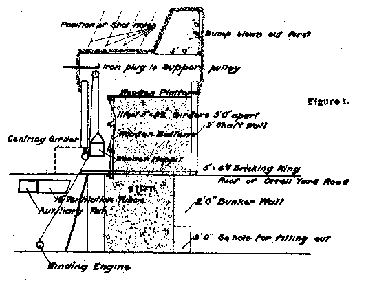
A short description of the method we used for "sinking upwards " may be of interest. The first job was to build bunker walls 2 feet thick as shown in Figure 1. These walls formed a square, with the centre of the proposed shaft at the centre of the square. The inside dimensions of the square were 8' x 8' and the outside 12' x 12'. A hole 3 feet square was left at the bottom of the wall so that the necessary dirt could be filled out to keep working room between the top of the dirt and the roof. A round of sumpers was drilled and fixed in the ordinary manner, and the debris allowed to drop inside the bunker walls. The side holes were then drilled and fired and the debris allowed to drop inside the bunker. As the holes were 6 feet deep it was soon possible to put in the first stretch of brickwork for the 12-foot shaft. A hole had to be left 4' x 4' in this stretch of brickwork, which was immediately above the bunker walls for the purpose of men getting into and out of the shaft. Two strong straight 18-foot girders were placed across the top of the hole to act as lintels. The girders forming the square of the shaft were the sills. A partition had obviously to be provided in the shaft itself. Wooden batons were bolted to the inside of each girder so that lagging boards, specially made, could be nailed to the inside. Thus a partition was obtained.
A second round of sumpers was fired and the side holes also drilled and fired, the debris in each case being allowed to fall inside the bunkers. It was now possible to build the second section of shaft lining, leaving in an 11-foot straight girder 3 feet away from the first one set. When two girders were in position the partition could be formed. The shaft was now looking "ship-shape," and ladders were erected for easy access to the face of the shaft. A separate ladder was used from the floor to the top of the bunker walls, and another ladder up to the shaft wall; this was secured by means of iron clamps driven into wooden bricks built into the shaft wall.
The problem of ventilating the rising shaft had to be dealt with, and this was solved by placing an auxiliary fan in the Orrell Yard roadway, and by suitable ventilation pipe bends the 18-inch ventilation tubes were got into the shaft. These were tucked away in the corner.
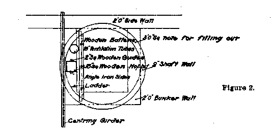
The problem of getting bricks, mortar, lagging boards, and 11-foot girders had now to be tackled, and to overcome this a compressed air turbine "tugger" was used. The rope from this auxiliary winder was directed up the shaft by means of pulleys, over a pulley which was suspended from an iron plug drilled into the side. Wooden guides were placed in the shaft, and a small wooden hoppit slid up and down the guides, which had to be well greased. A plan of the shaft (Figure 2) is shown on the diagram.
The ladder, hoppit, girders, and ventilation tubes fitted into an allotted space nicely, The shaft was now set out for sinking upwards speedily. Drilling the sump followed the ordinary routine, whilst the drilling of the side holes could be done standing in the shaft wall and drilling vertically upwards. After the firing of each round of shots it was necessary to fill just enough dirt out from the hole left at the bottom of the bunker to allow for headroom from the top of the debris to the roof of the shaft. Steel landing plates, reinforced, were used to cover up the open partition. An 18-inch circle door was left in one of them, and this placed directly over the ventilation tubes. When the shots were fired the fireman went up the ladder and opened the door, and the powder fumes and smoke were quickly cleared. As could be expected the holes did their work completely, and each sump and round of side holes was blown clearly.
The centring and verticality of the shaft could not be done by the normal centring methods. The 18-foot girders which we used as lintels for the top hole were placed accurately in position so that they formed the edge of the shaft on the inside, therefore it was necessary to build up to that line, which ensured verticality. Templates were used with care when placing in the brickwork round the shaft; this was kept vertical by dropping lines from the roof to the shaft wall already built below, and bricking to these lines. As the ground was blown down and the necessary debris filled out, girders were installed every 3 feet and the partition made. The ventilation tubes in 3-foot sections were extended, as were the ladder and hoppit guides.
(To be concluded).
 |
 |
| Names mentioned in this article | |
 |
 |
| Name | Age | Occupation | Notes |
|---|---|---|---|
| Carver, James | |||
| Latham, J. | Colliery Manager |
|
|
| Links to Collieries/Mines mentioned in this article | |
|
|
 | Garswood Hall Colliery |
 |
 |
| Related Articles | |
|
|
| Pub. Date | Article (Newspaper) |
|---|---|
| 26 Dec 1942 | Recovery Of Seam By Staple Shafts (The Science and Art of Mining) |
| 09 Jan 1943 | Recovery Of Seam By Staple Shafts (The Science and Art of Mining) |



 Contains public sector information licensed under the

