


| Newspaper Articles |

|
Newspaper Articles |
 |
 |
13th June 1942, Page: 338, Column: 1
Safety Provisions
Determination of Horizontal Candle-power
By "Tester."
Several kinds of photometer are available for the determination of the horizontal candle-power of safety-lamps by comparison with the light given by a standard lamp such as the Harcourt pentane lamp. The fuel used in this lamp is pentane, which, as the name suggests, is the fifth member of I he homologous series of hydrocarbons having the general formula CnH2n + 2C5H12 is a low-boiling paraffin having a boiling point of 36°C. and it is used in a 1-candle power Harcourt lamp, the flame of which is adjusted to a fixed height. Instead of using a pentane standard lamp an aged electric bulb may be used as a standard with the distinct advantage of an almost invariable standard of comparison at a specified voltage. Being provided with a suitable standard lamp we require a photometer of some kind.
The Bunsen Photometer.
The optical bench on which this photometer is used consists essentially of the
standard lamp, the lamp to be tested, and a screen of white paper upon which
there is a spot of grease or oil. The lamps are set up with the screen between
them, and the heights are adjusted so that the sources of light and the spot of
grease are all in the same straight line. The screen may then be moved in the
line between the lamps until both sides of it appear to be illuminated with
equal intensity, then the distances from the lamps to the screen are measured
to enable the candle-power of the pit lump to be determined. In the case of a
flame safety-lamp it was found that when the lamp was turned with the flat
burner it right angles to the line between the lamps, the distance from the
lamp to the screen was 100 centimetres, whereas the distance from a standard
lamp of 1 c.p. to the screen was 65 centimetres. It therefore follows that the
candle-power of the flame safety-lamp = 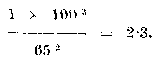 . In using the grease-spot photometer
it is usual to duplicate the test after reversing the photometer following the
initial determination.
The Rumford Shadow Photometer.
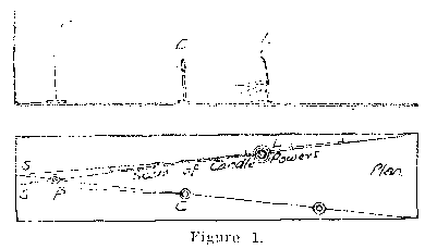
As will be seen on referring to Figure 1 this photometer consists of a sheet of
white paper mounted, in the vertical position at the end of a base-board upon
which an opaque rod, or pillar, has been fixed a few inches away from the sheet
of paper. The standard lamp, or candle, C and the pit lamp L, are placed in
suitable positions on two lines which pass through the pillar, and consequently
two shadows of the pillar are thrown on the screen near to each other. Either
the standard candle, or lamp, or the pit lamp is moved towards, or away from,
the screen until it appears that the shadows are of equal density. When
equality of illumination has been obtained the distances from the lamps to the
shadows cast by them are measured to enable the candle-power of the pit lamp to
be determined. In testing the candle-power of an electric hand lamp it was
found that when the standard candle was 1 metre from the screen the pit lamp
was 1.85 metres from it, therefore the candle-power of the pit lamp = 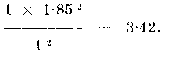 . The
modification of this photometer designed by Dr. Haldane is a useful
device for the rapid determination, without calculation, of the candle-power of
pit lamps. In using either the Bunsen or the Rumford photometer it is advisable
that the person making the test should shield his eyes from the direct rays of
light from the lamp, so that he may determine with reasonable accuracy the
position of the pit lamp at which the illumination of the grease spot or the
screen is the same on both sides.
The Lummer-Brodhun Photometer.
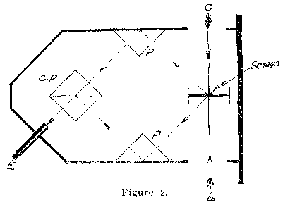
The construction of this device is indicated in Figure 2 as consisting of an
arrangement of four 45° glass prisms. Fixed in a central position there is
a composite prism CP consisting of two prisms placed with their hypotenusal
surfaces together, the plane of the junction being coincident with the plane of
a white matt screen placed midway between the openings admitting light from the
standard lamp, or candle, C and the pit lamp L to be tested. Other two prisms P
are fixed to the wall of the photometer in the positions seen in the figure,
and an eyepiece is attached to the enclosure with its axis normal to one face
of the composite cubical prism. It will be readily understood that the light
from the lamp L is reflected to the lower single prism from the screen, and
that the reflected ray is doubly reflected from the lower prism to the lower
half of the double prism, and then from the common hypotenusal surface to the
eye at B. The rays of light from that side of the screen illuminated by the
standard lamp C are reflected by the upper prism and pass through the composite
prism direct to the eye at E. The eye at E sees both sides of the screen and
can distinguish one surface from the other so long as they are unequally
illuminated, but when the photometer is moved along the optical bench until
both sides of the screen arc equally illuminated no distinction can be made.
Once again equality of illumination enables the candle-power of the pit lamp to
be determined in the usual way. When a standard lump having a candle-power of
2.35 was placed at a distance of 1 metre from the screen a cap lamp giving the
same illumination was found to be at a, distance of 2.80 metres from the
screen, therefore the candle-power of the cap lamp = 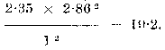
The Flicker Photometer.
In this instrument a specially shaped disc of plaster of Paris is rotated by clockwork about an axis which is coincident with the paths of the rays of light from the lamps to the medial plane of the disc. The medial plane occupies the position of the common plane of the composite prism in the case of the Lummer-Brodhun photometer, and the disc is so formed that the opposite sides of it can be seen through an eyepiece having its axis lying in the medial plane of the disc. When the opposite sides of the disc are unequally illuminated the light passing to the eye at the eyepiece appears to flicker, but when the photometer is adjusted until both sides of the disc are equally illuminated the flickering ceases. The ratio of the squares of the distances from the lamps to the medial plane of the disc expresses the ratio of the candle-powers of the standard and pit lamps in direct proportion.
The Photronic Cell Photometer.
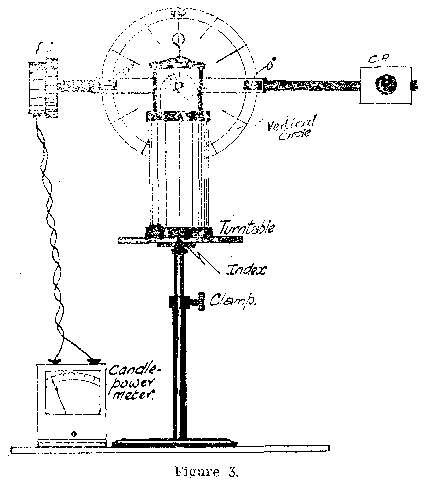
Figure 3 is a diagrammatic representation of a photometer in which a photo-electric cell is fitted to convert the energy of light falling on it into an electric current the voltage of which is proportional to the candle-power of the lamp emitting the rays of light. The photronic cell PC is mounted on an arm which is pivoted at the centre of a vertical circle divided into 10° divisions, and a counterpoise CP is fastened to the other end of the arm to preserve balance in all positions of the photronic cell. The lamp to be tested is placed on a turntable, and the height of the table is adjusted until the centre of the source of light is at the centre of the vertical circle. The turntable is divided into 10° divisions and is capable of being rotated horizontally to enable readings of candle-power to be made as the lamp is turned about its axis. A milli-voltmeter is connected to the photronic cell and is provided with a scale so that candle-powers can be read by the pointer direct and Without the need of calculation. The instrument must first be calibrated by placing a standard lamp on the turntable and adjusting the position of the cell on the arm until the candle-power meter gives the reading of the standard candle-power. The cell is clamped in that position and the standard Jam]) removed. A safety-lamp may then be placed on the turn-table and adjusted for height, when the candle-power can he read direct from the meter. The lamp can then be turned with the turntable into any desired position and the photometer can be raised or lowered so that horizontal and Vertical candle-powers can be determined.
 |
 |
| Names mentioned in this article | |
 |
 |
| Name | Age | Occupation | Notes |
|---|---|---|---|
| Haldane, John Scott, Dr. | Whos Who Page |
 |
 |
| Related Articles | |
|
|
| Pub. Date | Article (Newspaper) |
|---|---|
| 04 Apr 1942 | Safety Provisions, Mine Air Analysis. — I (The Science and Art of Mining) |
| 18 Apr 1942 | Safety Provisions, Mine Air Analysis — II (The Science and Art of Mining) |
| 02 May 1942 | Safety Provisions, Mine Air Analysis — III (The Science and Art of Mining) |
| 16 May 1942 | Safety Provisions, Firedamp Detectors (The Science and Art of Mining) |
| 30 May 1942 | Safety Provisions, Coal Mines General Regulations (Lighting), 1934 (The Science and Art of Mining) |
| 13 Jun 1942 | Safety Provisions, Determination of Horizontal Candle-power (The Science and Art of Mining) |
| 27 Jun 1942 | Safety Provisions, Horizontal and Vertical Distribution of Light (The Science and Art of Mining) |
| 11 Jul 1942 | Safety Provisions, Fire-fighting Regulations (The Science and Art of Mining) |
| 25 Jul 1942 | Safety Provisions, Causes of Underground Fires (The Science and Art of Mining) |
| 08 Aug 1942 | Safety Provisions, Prevention and Extinction of Underground Fires (The Science and Art of Mining) |
| 22 Aug 1942 | Safety Provisions, Fire-fighting Underground (The Science and Art of Mining) |



 Contains public sector information licensed under the

