


| Newspaper Articles |

|
Newspaper Articles |
 |
 |
29th June 1940, Page: 406, Column: 1
Change-Over From Steam To Electric Winding
By W. J. Leonard.
From paper on "An Interesting Change-over from Steam to Electric Winding" read before the June meeting of the North of England Institute of Mining and Mechanical Engineers.
Engine Built in 1875.
At the "A" Pit of the Bedlington Coal Co., Ltd., coal-winding has hitherto been carried out by a single-cylinder winding-engine built by J. and C. Joicey and installed in the year 1875. The stroke was 6 feet and the cylinder had a bore of 40 inches with steam-jacket. The safe working pressure was 40-45 lb. per square inch. The heavy piston was fitted with a tail rod. The total overall length of the engine was 43 feet. Drop-valves of the double-beat type, 11-inch diameter, were employed for admission and exhaust. The valves were hand-operated for starting, stopping, and riding men, but during coal-winding the operating handle was put into a gab for full-speed running. A single "loose" or slip eccentric was fitted for quick reversing.
The stop-valve was 12 inches in diameter. The drum was 14 feet 2 inches in diameter, and built up with two heavy cast-iron flywheels 20 feet in diameter and weighing 10 tons each. The crank-shaft was 16 inches in diameter and weighed 5½ tons. The drum barrel was formed of oak sections, bolted to flanges cast on the inner faces of the flywheels. This drum diameter was very important to the proper manipulation of an engine of this type. To one of the flywheel rims a band-brake was applied by means of a steam brake-engine and to the lower half of the other flywheel another band-brake was applied by a pedal operated by the driver's foot.
The depth of the lowest seam (the Harvey or Beaumont) was 789 feet and all coal was drawn from this depth, but it was necessary to call at the Main Coal, Five Quarter, Yard, Low Main, and Plessey Seams with timber, materials, and men. The weight of the loaded cage was 7 tons, and the maximum output of which the engine was capable from the lowest depth was 100 tons per hour.
The dimensions of the engine-house were 59 feet 10 inches long x 29 feet 3 inches wide, and 43 feet 6 inches from ground level to the eaves. All the walls were 3 feet thick.
In the month of March, 1937, new General Regulations in regard to winding came into force. These required special equipment for overwinding and reducing automatically the speed of the cages to not more than 5 feet per second on landing. As will be understood, the drum of the old winding-engine was unfitted for and incapable of withstanding with safety the severe stresses which this special equipment would produce. Although the engine was capable of drawing all the coal required from the Harvey Seam for years to come, it was thought advisable, both owing to its age and the requirement of a new drum and brake gear and looking forward to the future when it would be necessary to go down deeper, that it should be replaced by a modern winder.
At the Barrington Pit of the same Company there was a double-drum electric winder which was installed in 1927. This winder was of a very robust type and had been fitted with a new 50-period motor in the 1931 frequency change. The drums were 10 feet diameter x 4 feet wide, each driven through double-helical gearing by a 570 h.p. motor. Post-brakes were applied to each drum by deadweights under control of two compressed-air engines. Reversal of the motor was effected by means of oil-immersed contactors controlled by a master-switch connected to the driver's lever. The main incoming supply was controlled by a sheet-steel cubicle fitted with an oil-immersed circuit-breaker.
Transfer Decided Upon.
It was decided to dismantle the steam-winder — which certainly had been a grand old engine and given splendid service — and to transfer the electric winder from Barrington Pit, since it was found that this winder was fully capable of drawing an equivalent quantity to the old engine, also of reaching the lower seams, as well as being equipped with the special overwinding gear. The final change-over was to be made at some suitable week-end, and until that time the steam-winder must continue in full operation.
First of all it seemed that difficulty would arise in obtaining a proper rope lead to the pulleys. Owing to adjacent structures, only one position was suitable, and that was to the immediate left-hand side of the steam-winder. It proved possible to get the new drums behind and partly under the existing drum.
The height from ground level to the floor of the steam-winder was 21 feet. The floor level of the new winder was kept as low as possible and was fixed at 12 feet above ground level. To obtain a proper lead to the pulleys a considerable portion of the existing steam-engine pillar or foundation block had to be undercut to accommodate the bed-plate and right-hand drum of the electric winder. The depth of this undercut was 2½ feet. The width of the old drum was 6 feet 8 inches, and the two drums of the electric winder had an over-all width of 9 feet. Owing to the extra width of the latter, the rope lead showed itself to be yet about 2 feet out of the proper alignment. Any further undercutting of the old main engine pillar would have been too great a risk, and it was decided to offset the new engine and its foundations a few degrees from the centre line between the old drum and the centre of the "A" pit shaft. The headgear pulleys would be slewed a corresponding amount when the change-over was effected.
It may be thought that undue attention was given to this question of rope lead, but to those who have had experience with "straggling" ropes, any extra time spent in securing good layering is well worth while. The excellent layering of the ropes on the new winder justified the time and labour spent on this part of the work. The amount of brickwork excavated when undercutting the main engine pillar to accommodate the bedplate, drum, and main drum-shaft bearing was 1,120 cubic feet, and this part of the work was by no means the easiest, as the pillar had been built to stay and consisted of solid brickwork in cement mortar. The same substantial construction was in the 3-foot walls, one of which had to be taken out along the left side. Work was commenced by building the extension housing on the left of the old engine-house, this extension being built in 18-inch brickwork with inside dimensions of 43 feet x 17½ feet x 29¾ feet high. A fiat roof was formed and covered with Ruberoid laid on 2-inch boards and pitchpine principals. The extension is parallel and conforms with the existing building. When the side walls of this extension had reached their proper height of 29¾ feet the old engine-house wall on which the extension abutted was removed.
The work of dismantling the electric winder was finished and the various parts brought to the "A" Pit. With the exception of slight hindrances, the erection of the new winder went on smoothly, certain portions of brickwork being hacked out which were in the way of post-brakes, etc. Steam- and exhaust-pipes were moved where they fouled essential parts of the new equipment. The large 18-inch diameter exhaust-pipe which had been outside and rising up the left-hand wall of the old building had been previously shortened and led through the roof of the old building. It was not possible to couple up the post-brake system of the new winder until the main steam-pipe had been removed, but a series of no-load runs was given to ensure everything being in order prior to changing over.
It was decided to start the change-over on the Thursday midnight before Good Friday, 1939. The work proceeded without incident and to such good effect that men were riding in the shaft on the Saturday afternoon, 40 hours after the old steam-winder had stopped. Coal-drawing was resumed on Easter Tuesday, and it was only necessary to go quietly about the work of pulling down the very large pillars of the old engine and finish off the engine-house as a whole.
An interesting thing was noticed when the heavy flywheels of the old drum were being dismantled. These wheels were cast in halves and secured to the shaft by large cotters driven through the rim and contracting hoops, 3½ x 2½-inch section, securing the halves at the boss, whilst eight flat keys were used between the boss and the crank-shaft. The top half of the flywheel was slung to a roof balk, leaving the "split" of the flywheel horizontal, and when the contracting hoops were burnt through and the rim cotters driven out, the bottom half refused to fall clear. Wedges were driven into the split and it was seen that sal-ammoniac and metal borings had been employed to make a tight job. In early days when accurate machining of heavy components was impossible this method of making tight joints was often employed and the effectiveness of the rusting action which followed can be judged when, in this case, 5 tons of metal were held against gravity.
Description of Valve Gear.
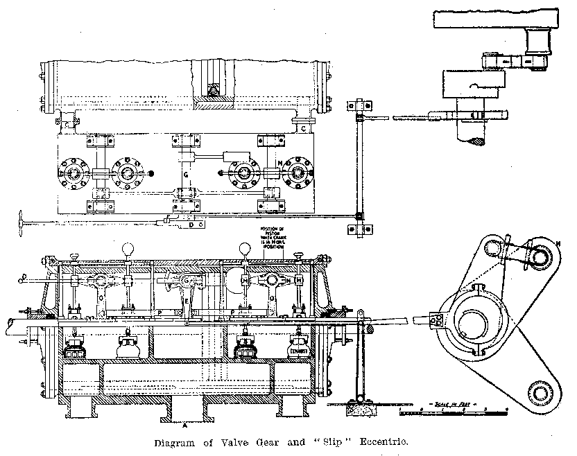
It is interesting to note the operation of the valve gear of this engine. The accompanying illustration shows a plan view of the steam-chest and part of the cylinder. Underneath is a sectional elevation of the steam-chest partly cut away to show the operating levers and valves. Steam is admitted at A and passes through the steam-valves B to either end of the cylinder by way of the ports C. The main stop-valve, which is not shown, was always open and functioned only in the case of an overwind or overspeed. Unlike the majority of steam-winder valves it did not function as a regulating valve. The whole of the regulating was done by the engineman admitting steam through valves B by raising the hand-lever D. The quadrant, E, E1, is connected to the single eccentric from the drop-arm E. The gab E1 forms the other hand of the quadrant. The quadrant is loose on the centre shaft G and the handle D is bolted to G. The engineman swings the lever outwards, thus disengaging it from the gab, and he is then free to open steam- or exhaust-valves at will.
The drum diameter is made up so that at the end of each wind the crank stops with the piston one-quarter of a stroke from the front end of the cylinder. Assuming that one cage is at bank and the crank in position H with the piston one-quarter from the end of its forward stroke, reversal is obtained by admitting steam to the front end, and the engine acquires sufficient momentum to overrun the back centre. When speed is obtained by this hand-control the lever is put into the gab and the eccentric operates the valve gear throughout the wind until the cage is within about two drum revolutions of the pit bottom. The engineman then takes control by disengaging the lever from the gab and brings the cage to rest by hand operation. It will be remembered that when the cage was at bank the piston was one-quarter from the end of its forward stroke. It is in exactly the same position when the cage is at rest in the pit bottom, but the crank is in the low position L. Reversal is again obtained by admitting steam to the front end. On every trip the crank is alternately above and below the forward centre. If the crank is moving clockwise it stops on the high centre H; conversely, if running anti-clockwise it stops on the low centre L. To permit of this control, careful rope measurement and adjustment were necessary. Minor adjustments were made by saddling. The time taken to put on a new rope was 6 hours.
For reversing the engine a simple device, which we may call a "slip" eccentric, was designed and the details of this are shown. The eccentric was allowed to swing on the shaft for half a turn, or, in other words, when the crank-shaft commenced to rotate the eccentric did not move until half a revolution of the crankshaft was completed. The piston then being over the back centre of the cylinder, the eccentric was in position to operate the valves in the particular direction of running.
The valves were lifted by knuckle joints M from each rocker arm N. The latter in turn connected from their drop-arms O with connecting rods to the quadrant E, E1.
It may be of interest to note the height from ground level to the old steam engine-house floor. This was 21 feet, and like many other old winders it was considered of the utmost importance in those days to bring the engine up to banking-out level, so that the engineman should have a full view of the cages arriving at bank. Sixty-five years ago, when the steam-winder house was built and a new iron headgear erected, a grave complication had evidently arisen. The west side backstay which abutted on the engine-house front wall was dead in the engineman's line of sight. Imagination must now play its part and one can picture the horror on the faces of the enginemen concerned and their urgent requests to the owners to remove the offending backstay. The owners must have gracefully acceded to their pleas, since measurements taken sixty-five years later revealed the fact that the baskstay had been moved outwards a distance of 4 feet from its proper symmetrical position, thus giving to the enginemen an unobstructed view of the "rituals," at bank.
 |
 |
| Names mentioned in this article | |
 |
 |
| Name | Age | Occupation | Notes |
|---|---|---|---|
| Leonard, W. J. |
|
|
| Links to Collieries/Mines mentioned in this article | |
|
|
 | Barrington Colliery |
| | Bedlington Colliery |




 Contains public sector information licensed under the

