


| Newspaper Articles |

|
Newspaper Articles |
 |
 |
4th May 1940, Page: 340, Column: 1
Endless Rope Haulage
Working to the Dip
By E. H. Browne, B.A.Cantab.
From paper on "Endless Rope Haulage: Large Installations Working to the Dip," presented at the April meeting of the Manchester Geological and Mining Society.
Importance of Planning and Layout.
This paper is an examination of certain aspects of large over-rope endless haulage installations working to the dip. Brief mention only will be made of certain special features of design of the gear itself. The choice of the over-rope system as the subject of the paper is not dictated by any preference for that system.
As haulage requirements are directly dependent upon the planning and layout of workings, it is necessary to refer to these. Many of the difficulties which have to be met with in haulage installations are due to indifferent planning design. The concentration of haulage roadways and the limitation to a few feeders is an essential requirement for economical working, and this can only be achieved by sufficient forethought and planning work. Detailed layout of haulage installations is also vital. Gradients throughout the roadway must be considered and regrading provided where justified. A section showing the rope in its full length should be examined if undulations or changes in gradient, however slight, are present.
Standardisation.
It is extremely unfortunate that in this country little if any progress has been made in standard specification of haulage requirements, whilst in America and on the Continent much has been done. Starting first with roadway sizes, a great simplification would be effected if steel arches were standardised. This would probably help rollers of steel, particularly during war-time difficulties. Rails, sleepers and tubs, including tub wheels and drawgear, should certainly be included in standardisation. With the haulage gears themselves something might be done, but this is of less importance. Incidentally, there is a special case for early consideration of locomotive requirements, as development of this type of haulage will undoubtedly extend.
It is to be deplored that up to now no appreciable achievement in standardisation can be recorded in mining equipment. It may not be possible to effect conversions at many pits, but guidance for new installations would be available, whereas at present no indicated lines are offered and there is little hope for future improvement.
Preliminary Examination of Requirements.
The calculations of power required and maximum rope tension are elementary matters. There are various methods of approach and empirical allowances to be made. It is not intended to give details of any method of estimation, but reference will be made to one or two of the factors to be considered, as follows :—
Output. — For the purpose of calculation only 2/3rds of the total running time should be used.
Size of Tub. — This will be a fixed condition unless a new installation of tubs with consequent expenditure is envisaged. In the latter case few will consider advisable the installation of tubs with a capacity less than 18 cwts., whilst where particular circumstances are favourable the 3-ton tub would be chosen. Too small a tub is the millstone of many pits, particularly in Lancashire. The installation of 18-cwt. or larger tubs may be prohibited owing to the cost of roller bearings, etc., modification of winding equipment, cages, creepers, tipplers, etc., and perhaps even shafts are inadequate in size. Some appreciable improvement in capacity may be obtained cheaply by increasing the height of the tubs on existing frames.
A small tub size will effect the design of the installation, although not the h.p. nor the rope tension appreciably. It may affect the maximum output which can conceivably be drawn through one road, as the ultimate factor will be the number of tubs which can be handled at one point. As to type, future design will probably follow American practice in the welded tub with well bottom close to the ground.
Rope Speed. — Whilst the h.p. will not be affected the rope tension will vary inversely as the speed. The slower speeds are therefore to be avoided. Less than 1¼ m.p.h. is not recommended, whereas speeds above 1.6 m.p.h. may lead to difficulties in attachment and detachment of tubs to the rope.
Factor of Safety of the Rope. — This is a very vexed question. For larger installations the rope becomes a major problem, and the factor of safety which can be obtained is lower than that adopted in other branches of engineering. Rope manufacturers in this country suggest a factor of safety of 5 to 7, whilst the American Engineering Standards Committee give a minimum factor of 4½, but this may be assumed to apply primarily to direct rope haulage, and is exaggerated for endless rope requirements. In any case British ropes are of a vastly superior order to American. On the other hand, an enquiry into factors of safety of ropes operating throughout this country would show some extraordinarily low figures, many of which would be open to criticism.
Slow speed endless rope haulage does not subject the rope to severe dynamic stresses nor sudden shocks associated with winding and direct haulage. The provision of proper electrical overload protection should eliminate prolonged acute stresses on the rope. Even so, the lowest factor of safety which should be accepted is 3.5 whilst 4 should be obtained if practicable. It must not be forgotten that the rope at the end of its life will carry the same load as on the day it was new, although later by wear its breaking stress may well be considerably reduced. The strength should be subject to observation throughout the life of the rope. As in other branches of engineering the factor of safety based upon the breaking stress is a wrong conception ; the yield point is the critical factor, as beyond this distortion and fatigue will occur.
General Layout.
Having ascertained the power required and the maximum rope tension, the general layout may be considered. The bankhead is an important feature and is influenced by (1) Consideration for the rope with provision against wear and damage ; (2) Position of the haulage gear ; (3) Facilities for tub handling and manpower.
1. Consideration for the Rope. — As this depends upon the choice of the rope the two matters will be examined together. The product of the factor of safety desired and the maximum rope tension determine the tensile strength required. A flattened strand rope should be used to give maximum wearing surface and greater strength for diameter, in standard construction such as B.S. 237 (6 strands of 10 wires each, 7 over 3 wires forming a triangular core, hemp main core).
Greater ductility is, of course, obtained in the lower qualities of steel wire, and where possible 90-100 tons per square inch breaking stress should be used. Where diameter or weight of the rope is a limiting factor 100-110 tons per square inch material will be selected, but the higher qualities are unsuitable for ordinary haulage purposes, their application, particularly in the case of 115-125 tons per square inch wire, being limited to deep winding requirements.
In the choice of basic or acid grade the latter is usually recommended, but nowadays the grounds for so doing may be weaker than generally imagined. The claims of acid grade for wire rope are well known, but basic grades are so improved to-day that the advantages of the former may in the future be proved insufficient to justify the extra cost.
This digression has been necessary in order to consider fully the selection of the rope. This done, the demands of that rope must be examined. For a large installation it will be an expensive item and deserves treatment accordingly, apart from the essential demands of safety. The elimination of pulleys wherever possible must be aimed at; when necessary they must be of adequate size related to rope diameter. This applies in particular to the surge wheel of the haulage gear. There are systems where, for instance, 1 1/8" ropes pass round 4' diameter wheels and the arrangements are claimed satisfactory ; the life obtained from such ropes cannot be more than a fraction of that which could otherwise be achieved.
A good rule is to make pulley diameter 100 times that of the rope, whilst 70 is the minimum which should be permitted. The American Engineering Standards Committee recommends for 6 x 7 rope construction a ratio of 96 for pulley/rope diameters.
The following table shows the minimum and recommended limits mentioned :—
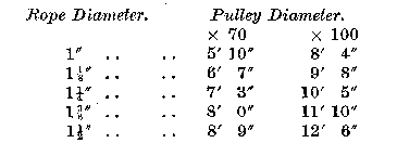
Where the rope is under tension a quarter turn round a pulley has the same effect as a full turn. Pulley diameter should be within these limits, except where deflection is small or at the bottom of the brow where tension is low. In the latter case the return frame may usually suit the distance required between ropes.
On the other hand, the surge wheel of the gear and the return pulley behind it must conform to the rules given. The latter presents a difficulty in larger installations. For instance, in a case of a 250 h.p. haulage a 10' diameter surge wheel and a 10' return pulley are chosen. Now the distance required between ropes in the roadway is unlikely to be as wide as 10', especially if the travelling way is on one side of the road, so the empty tub rope must be brought in to this distance by another pulley, also of diameter suitable for the amount of deflection. Pulleys are to be avoided, yet it is preferable to have the addition of one of correct size than to bring the rope round a return wheel of too small radius.
Rope pressure on top of the tubs must be limited, and the position of the rope in all parts of the roadway should be examined on a large scale section. Towards the top of the brow, where the tension is the maximum, the rope must either be clear of the top of the tubs, or if unavoidable, be deflected so slightly that the downward force on the tubs does not exceed 1 ton. This force can be easily calculated from the rope tension and details of gradients. In the 250 h.p. case quoted the maximum rope tension was 27 tons, thus the load permitted to be carried by the tub was only a small fraction of the total.
At the bankhead itself the rope should be entirely clear of the top of the last set of tubs and pass straight on to the surge wheel without deflection of any kind. No scheme for a major installation can be considered satisfactory unless this provision is obtained.
2. Position of the Haulage Gear. — This may be prescribed by the nature of the strata or the manner in which it has been cut up. The strata may be unsuitable for a large excavation in the roof. But for over-rope haulage this is frequently the best place, and where the delivery roadway is in line with the haulage brow it is the only place. If the dip roadway under consideration intersects the level to which the tubs are to be delivered at a right angle or thereabouts, the gear may be installed on the opposite side of the level, although the haulage gear has to be lifted higher rapidly as the position becomes more remote from the actual bankhead.
3. Facilities for Tub Handling and Manpower. — The handling of tubs must be catered for in detail. When over the top they should run freely to the position required. The operation of unlashing or unclipping the sets must be analysed closely, and allowance made for a margin for momentary difficulty or miscalculation on the part of the haulage hand. If the requirements of the rope detailed above are to be met, it is difficult with gradients steeper than 1 in 4 to provide the necessary facilities for the detachment of full tubs.
To allow sufficient time for the haulage hand to unlash full tubs various methods may be adopted. Provision for the rope to be within easy reach may be obtained by the erection of a platform, whilst in larger schemes a creeper is required to pick up the full tubs at a speed slightly greater than that of the rope, thus releasing the load on the chain or clip to permit detachment.
These three factors affect bankhead design fundamentally, and must be borne in mind when deciding : (a) The bankhead length and gradients of full and empty tracks ; (b) The radius of the curve of intersection.
Too often a bad start is made by the use of existing excavations instead of making further extensions. To reduce manhandling the length of the bankhead should not normally exceed 30' whilst frequently it can be less. Pull and empty tub gradients are adjusted to allow the tubs to run freely when detached, and if possible to release tension prior to this to effect the detachment.
If the gradient cannot be so devised to allow this, then a creeper arrangement may be employed. Every case must be examined intrinsically and no conventional treatment is possible.
(To be continued.)
 |
 |
| Names mentioned in this article | |
 |
 |
| Name | Age | Occupation | Notes |
|---|---|---|---|
| Browne, E. H. | Whos Who Page |
 |
 |
| Related Articles | |
|
|
| Pub. Date | Article (Newspaper) |
|---|---|
| 04 May 1940 | Endless Rope Haulage, Working to the Dip (The Science and Art of Mining) |
| 18 May 1940 | Endless Rope Haulage, Working to the Dip (The Science and Art of Mining) |



 Contains public sector information licensed under the

