


| Newspaper Articles |

|
Newspaper Articles |
 |
 |
10th February 1940, Page: 241, Column: 1
Fires In Mines
By Chas. W. Brown.
From paper on "Some Causes of Mine Fires — Their Prevention and Methods of Combating," read before the North Staffordshire Colliery Undermanagers' Association. Concluded from page 235.
Fire-fighting Arrangements.
So much for the "causes" and "prevention of" underground fires, but we may at some time or other be faced with the condition of fire, so that we should be at all times in a position to deal with any such occurrence at any point of the mine by the installation and maintenance of some kind of "fire-fighting" system.
It is quite obvious that, owing to variation in geological conditions and other variations met with in mining, no hard and fast rule can be laid down with regard to any system adopted, but in most cases some means are possible to achieve the same end, that is, to be able to deal with a fire! Thus, in the case of a mine having workings mostly in the "dip" a system of "tanks" which may be made at any fixed point of concrete holding (say) some 2,000 gallons of water at all times, and having a column of pipes with suitable hydrant connections for the attachment of fire hoses at all necessary points.
In the case of a mine with rise workings, it then becomes necessary to install a pump or pumps to force a supply to the necessary points, or if there is a pump at the pit bottom pumping to the surface, special connections may be made to supply fire fighting pipe lines, or again, it may be possible to tap the rising main pipes at a point where the head would not be too great for the size of the fire-fighting pipe column.
Whatever system is in use, the appliances should be of a simple nature, and such as to be understood by a sufficient number of reliable persons on all shifts to ensure a staff for fire-fighting at all times. Such a staff should be made up of persons mostly situated, during their ordinary working periods, in close proximity to "key" points and telephonic communication points, and in order to ensure efficiency in case of necessity "fire drill" should be periodically practised with the actual appliances adapted to the system. The whole operation and direction of every item in the system should be in charge of one person whose duties would include a periodical inspection of the whole system, making a report in a special book provided for the purpose. He should note any deficiencies in the system, and order any parts necessary. His duties would also apply to all other appliances such as extinguishers, sand buckets, stone dust buckets, in short, everything to be used as a means of putting out a fire. This latter person would be designated the "Fire Chief," and since he would not be at the colliery at all times he should so instruct responsible persons on each and every shift as to be able to act should necessity arise. It may be advisable to supply each shift representative with a general sketch plan containing the necessary instruction as to the use of valves, etc., contained in the water system. This may present a difficulty since the conditions in any one mine are changing from time to time, but when a person adapts himself to any one system he would be able to grapple with any change, since the appliances used would be similar in all cases.
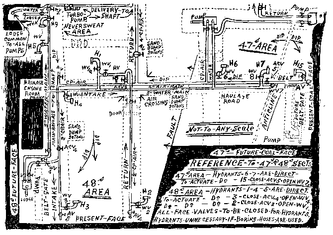
The writer happens to be in the position of "Fire Chief," and so is able to give an illustration of a portion of a fire-fighting system. In the sketch it will be seen that the mine is, as most mines are, split up into districts with names of each which may be applicable to any other mine. The sections here shown are "48's," and "47's," and Neversweat. In this case the system is made up of two separate sections, that is, 47's and 48's are coupled together in one "water" system, while the Neversweat is served by a separate one. Upon examination of the sketch plan, noting the respective positions of the several pumps it will at once explain that the contour gives a dip in all directions again, it will be noticed that all the pumps are coupled to the one general pipe system, whilst at the same time the same pipe system is coupled for emergency purposes to the "Turbo" pump shown in the Neversweat section, which pump deals with the water from a lodge which serves as delivery point for all other pumps of the pit. Under general conditions this pump pumps up to the shaft bottom, but should the "head" from other pumps fail or be insufficient in case of fire in the two sections 47's and 48's, then by closing the valve WVX, which closes the delivery of lodge from other pumps, opening valve on pipes leading from the turbo pump to lower system pipes WVZ and closing valve WVZ, the districts 47's and 48's are supplied.
Under normal conditions, providing the pumps are in order, the turbo pump would not be required as the various heads would serve, but it was thought wise to provide a duplicate means. In the vicinity of the turbo pump there is at all times a person on hand and a telephone capable of dealing with necessary requirements should a 'phone message be received from any point. In close proximity to the same person are stored at all times 600 feet of canvas hose pipe with nozzles suitable for the hydrants shown in sketch at various points ; also in the "fire" store on the surface there is another 600 feet which may be sent into the pit if required. Hydrants are connected to the pipe columns in the most likely places, and are so arranged that one at least will be on the intake side of any likely fire and also be placed in relation to the available length of hose. In the Neversweat area the system is coupled to an electrically driven 3-throw pump shown in sketch.
It will be noticed that in neither of the three sections do the water pipes extend to the working faces, except the section 47's, where the pipes are shown in dotted form to indicate their future positions upon the change-over from a finished area to a new one. This is shown as "future coal face," thus confirming what has been previously mentioned of changes occurring in mines from time to time, and the difficulty of producing any form of "fixed" plan or system in use. The method adopted to obviate the extensive use of water pipe column is to make use, as much as possible, of the compressed air pipe column used for shothole boring, jack picks, etc., on the faces. A system of crossover valves is made use of in the manner shown in the various sections, thus, in 48's section, the cross connection is made from the "main" water column at a point below the delivery into it of a pump situated some 25 yards to the "dip" side of 48's face, which pump is stationary and of no use for fire-fighting purposes except for its water which it delivers into the main system. It will be seen that the connection is made by a crossover pipe, in this case a flexible 2" hose owing to its having to be passed underneath a conveyor belt, from the water to the C.P. air pipes with a valve WV4 in the connecting pipe.
In the air column a little above the connection is a valve whereby, in case of fire, the C.P. air may be cut off, and also at the end of the metal C.P. air pipe beyond the hydrant 3, is another valve A.V.S., thus the lire hose may be connected to hydrant 3 and water turned on by opening WV3.
So much for the main gate-end of 48's section. In the return it will be seen that the arrangement is little different but serves the same purpose of leading the water into the C.P. air column to serve the hydrant 2 shown at the face end of the road. In this case the means of connection is from the vertical column upon which the hydrant 1 is fitted from below the hydrant valve WV1. A short 2" pipe leads the water into the C.P. air column. In the latter pipe is fitted a valve WV1, the "separation" or "air cut-off" valve ACV2 being closed to exclude C.P. air. When the water is required for the C.P. air column WV1 is opened, and the C.P. air valve AV4 at the face end is closed, so that the hydrant 2 may be used for hose connections, the water being passed by opening the valve WV2. The valve R.V. in the crossover section is for the purpose of periodically testing the efficacy of the arrangement; in order to do this the valve A.V. shown between the separation doors is closed to prevent water passing through the C.P. air pipes to the detriment of boring operations. Similar arrangements are made in regard to the ether areas.
On all working faces "stone dust" buckets are provided, one for each waste, and are hung on the steel props by specially constructed hangers as shown in FIGURE 2. These hangers are fastened to the bucket handles so that they cannot readily be detached, thus avoiding loss. They are kept filled with stone dust. The general practice is to empty them for stone-dusting all the packs walls and refilling them with fresh dust each morning. Also at each switch six bags of stone dust arc provided. The latter is used and replaced daily in order to insure the supply being in a "fresh" state at all times, but apart from dust used at any other points, the strict rule is to keep the six bags there at all times.
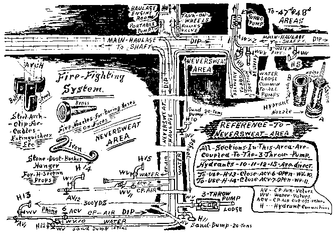
On each coal-cutter machine are fitted two small fire extinguishers which are encased in specially designed cases (shown in FIGURE 3), which are in the form of two short metal pipes welded together, one end being sealed as shown at A, the other end having a throwover cover as shown at B, the whole being welded upon the machine cover, which latter is duly bolted to the machine, These cases are of sufficient strength to withstand the rough usage incident to mining work, but to meet the contingency of one of them becoming damaged a spare cover with a case attached is kept ready in the stores on the surface, as the welding cannot be done underground.
At the cover ends, inside, in order to prevent the extinguishers being unduly actuated by the continuous jolting of the machine, two 3" pieces of 2" pipe are fitted over the tappet ends, thus preventing the tappets from coming into contact with the cover.
In close proximity to each switch and motor are hung, by special "clip" hooks to the roof supporting arches, two gallon "aquamatic" fire extinguishers (the type of clip being shown in the accompanying sketches), together with sand buckets full of dry clean sand, with suitable covers, while in addition there are kept ready not less than six bags of stone dust which is regularly replaced in order to ensure its efficacy in case of necessity.
On the working faces buckets are kept full of clean stone dust hung to the supports by specially designed hangers, the latter, and the method of its use, being shown in FIGURE 2 (See last issue). Other sketches show their form of construction for easy use upon the H-section props. One of the buckets is hung opposite each waste, and the buckets are refilled each morning with fresh dust, the old dust being distributed along the pack walls, thus aiding in the dilution of coal dust prevalent in such positions.
In order to facilitate the "more direct" use of water directly on the working faces, special nozzles (of a type shown in sketch) are provided for use upon the ends of hoses used for shothole boring, which obviates the necessity of sending for the hydrant hoses from the store, and thereby saves much time, which is so valuable in case of fire.
It is the duty of the "Fire Chief" to examine the whole of the fire-fighting system monthly, opening out all extinguishers, trying all hydrants, both on the surface and underground, reporting upon the same in a book specially provided for the purpose, noting only discrepancies and advising upon any necessary additions to the system.
In addition to the foregoing, the importance of sand dumps should be mentioned, because in case of necessity it would be almost impossible to import any quantity of sand to distant parts of the mine. The position of such dumps, together with the position of hydrants and valves, is shown in the several sketches, whilst the use of valves is shown inset in each case.
A further addition to the system is the provision of "hand" portable pumps which, with all the necessary fittings, hoses and nozzles, and also tanks on wheels full of clean water with means of refilling, are kept in places where, and from whence, their use may be adaptable in case of fire. In all the fire-fighting system the staff, or persons situate on each working shift, at key points, are well versed in the use of the whole apparatus, tests being periodically made as to their efficiency.
 |
 |
| Names mentioned in this article | |
 |
 |
| Name | Age | Occupation | Notes |
|---|---|---|---|
| Brown, Charles W. |
 |
 |
| Related Articles | |
|
|
| Pub. Date | Article (Newspaper) |
|---|---|
| 13 Jan 1940 | Fires In Mines, Some Common Causes (The Science and Art of Mining) |
| 27 Jan 1940 | Fires In Mines (The Science and Art of Mining) |
| 10 Feb 1940 | Fires In Mines (The Science and Art of Mining) |



 Contains public sector information licensed under the

