


| Newspaper Articles |

|
Newspaper Articles |
 |
 |
27th January 1940, Page: 230, Column: 1
Backstays For Use In Mines
In the last issue of THE SCIENCE AND ART OF MINING reference was made to the publication of S.M.R.B. Paper No. 103 on "Backstays for Use in Mines." The attention of owners and managers has been drawn to the document in Mines Department Circular 128, and it is pointed out that the failure of a backstay — also known as a jock, bar-hook or drag — is a fairly common occurrence which sometimes has distressing results. It was because of this and because it was suspected that in some instances the failures were due to poor design, that an investigation of the various designs of backstay in current use was put in hand. Representative types of backstays were obtained from several coalfields, and it was found that they could be roughly classified into four groups according to the method of attachment to the tub. Controlled tests were then carried out on two experimental tracks having gradients of 1 in 4 and 1 in 15 respectively. These tests showed that many of the backstays in current use could be greatly improved upon. Two of the types tested, both of which are in common use, viz., one with a hook to be dropped in the drawbar eye or link, the other with a link to be hung on the drawbar hook, are particularly liable to be over-ridden by the tub, unless, with the latter type, part of the stay projects beneath the tub. Over-riding also occurred with backstays of the type designed for attachment to the tub axle. Mr. F. H. Wynne, H.M. Chief Inspector of Mines, feels confident that at mines where backstays are used the careful application of the principles explained in Paper 103, with regard to the details of design and the quality of the metal used, would enable mine managements to prevent not only many accidents from runaways but also many irritating interruptions of transport arrangements, with their attendant loss of output and damage to property.
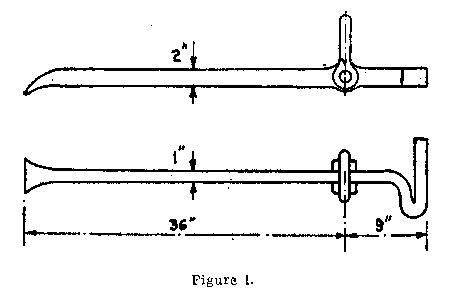
In the introduction to the Paper it is recalled that, over a period of eight years, 248 per cent. of the deaths from haulage accidents were due to runaway tubs. A runaway may be due to one of a number of causes, such as failure of drawgear, rope capel, rope or lashing chain; loss of control at the engine or accidental uncoupling; failure to secure tubs properly, or other errors of judgment on the part of the operatives. Paper 103 deals with one method of arresting potential runaways, namely, that of attaching a strut to the end of a tub or set of tubs. The tests were carried out on two tracks with gradients of 1 in 4 and 1 in 16 respectively. The backstays were attached to one of two types of tubs. The drawbar of one had a hole punched in the end for attaching a hook or shackle, the other had a drawbar hook.
As a preliminary to the experiments representative types of backstays were obtained from several coalfields in order that the variations in design could be examined. These backstays were found to differ widely in almost every detail, the variation in weight, for instance, being from 9¾ to 72 lb., and the variations in length from 23 to 42 inches. It was possible, however, to make a rough classification into four groups (A, B, C, D) depending upon the method of attachment to the tub.
Results of Experiments.
In the summary of results in the accompanying table, a figure "1" indicates that the backstay acted satisfactorily, i.e., the tub or tubs were arrested safely either with or without derailment, "½" indicates that the tub or tubs were arrested but that the backstay was holding them insecurely, "0" indicates failure of the backstay to effect a satisfactory arrestment, whilst a denotes tests which were not carried out as failure was certain.
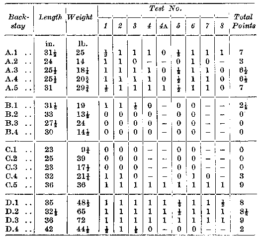
Discussion of Results. — Backstays attached by hooking into a drawbar eye or to a link, or attached by a link to the drawbar hook (Groups B and C), form a very large percentage of those which are in general use and, with the exception of C5, i.e., with part projecting beneath the tub, have proved the least satisfactory. Failure was almost invariably due to the backstays being overridden. In the majority of cases this took place without derailment of the tubs.
Over-riding without derailment also occurred in some instances with the backstays attached to the tub axles (Group A), but the action in this case was somewhat different. With those in groups B and C, the rear pair of wheels was forced up off the rails and lowered on to them again, whereas with group A, due to the small angle of inclination to the track, the backstays slipped sideways between the rails and the floor, and the wheels remained in contact with the rails. Where over-riding brought about derailment it was found that on both gradients the tubs in some tests continued to run away, and on this account any arrestment where overriding had occurred was not considered as being entirely satisfactory.
The only completely satisfactory backstays were C5 and D3. D1 and D2 were also very good but failed eventually due to bending of the drawbar end when holding under severe test conditions. The one feature common to these four backstays, and contributing to their good performance, was that over-riding could not take place without fracture or bending of the backstay or drawbar. Backstays attached to the drawbar proved most satisfactory. In practice three points are available for the attachment — (a) the axles, (b) the drawbar and (c) the yoke. Backstays attached to the drawbar are considered to be the most satisfactory type. The use of the yoke is the least common and is only practicable where the forces involved are not large, as this point of attachment is weak.
In the case of (a), providing the backstay grips in the road without penetrating too far, the tub will tip forward rather than over-ride. It has been shown, however, that the small inclination of the backstay to the track allows it to slip sideways under the rails, especially if the sleepers are above road level or if the floor is soft. Further, if the pedestals holding the axle are weak they may break and allow the tubs to run away.
Attachment at (b), the drawbar, provides the strongest point of attachment because the backstay then acts directly on the frame of the tub. It is also convenient for the operative to reach and permits the extension of the backstay beneath the body of the tub to prevent over-riding.
In the summary (table), it will be seen that the shorter backstays gave the worst results. Some values have been calculated for the minimum length necessary to hold stationary tubs under the conditions of test used, and these show an apparent superiority of the axle backstays (group A) which, however, is not realised in practice due to their tendency to slip sideways, thus reducing the effective length. These calculations apply only where no impact is involved when buffing up or a run-back occurs the length of backstay required to hold under a given set of conditions will be much greater.
Conclusions.
Method of Attachment. — The essential requirement in the design of an efficient backstay is that it must not permit the radial movement of the backstay about the point of contact with the floor to allow over-riding to occur. This condition can be met with a rigid backstay attached by a link to the drawbar hook a short distance from the end, so as to allow part of the backstay to project beneath the body of the tub, and also by those attached to the drawbar by a pin through the forked end.
Length. — Whilst it is possible to prevent over-riding and to arrest a set of tubs under the worst conditions by an appreciable increase in length and cross-section of backstays, practical considerations of weight and portability determine that the maximum length possible is from 3 to 4 feet. Over-riding must therefore be prevented by one of the above methods of attachment.
Weight and Cross-section. — The bending moment on a backstay is reduced as the length is increased because the inclination of the road is less, but, for a given weight, increase in length without reduction in resistance to bending is only possible by the use of special sections, e.g., tubular or angle sections.
For an overall length of 3½ feet and a cross-sectional area of 2 to 2½ square inches, the total weight for a backstay of type C5 would be approximately 35 to 40 lb. These figures are suggested as minimum values and should be increased where the weight of the set hauled is large or the gradient very steep. The maximum practicable weight for a backstay is about 70 lb., but clearly the danger of making a backstay too cumbersome to use must be avoided.
General Construction. — The end of a backstay should be flattened to a chisel edge to ensure that it will grip the road quickly. It should not be forked as the fork may ride on the rail or, in some cases, on the tail rope.
For maximum strength the main portion of a backstay should consist of a straight bar. Where double prongs are used as, for instance, for the provision of the attachment of a tail rope, the suggested minimum weight should be increased to ensure that the combined strength of the double prongs equals that of the single-prong backstay.
The coupling link or hook should be of adequate dimensions and at least equal in strength to the drawbar couplings. Welds should, if possible, be avoided.
Material. — The materials used in the manufacture of some typical backstays are either mild or dead soft steel, materials which are relatively weak and easily bent. In view of the heavy duties which backstays have to perform, and the need to make them reasonably light and portable, it is clear that material of high quality should be used and 1.5 per cent. manganese mild steel is suggested. This material has already been recommended as suitable for colliery haulage drawgear.
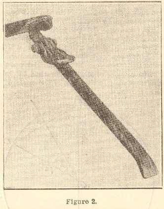
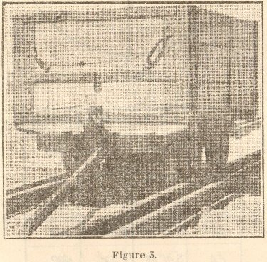
FIGURE 1 shows backstay Group C5; FIGURE 2 is a suggested design for a backstay; and FIGURE 3 the operation of the backstay.
 |
 |
| Names mentioned in this article | |
 |
 |
| Name | Age | Occupation | Notes |
|---|---|---|---|
| Wynne, Frederick Horton | H.M. Chief Inspector of Mines | Whos Who Page |




 Contains public sector information licensed under the

