


| Newspaper Articles |

|
Newspaper Articles |
 |
 |
27th August 1938, Page: 54, Column: 2
Improvements In Light Distribution From Miners' Electric Cap-Lamps
By Prof. W. H. Mcmillan, B.Sc., F.R.S.E., and S. Holmes, B.Sc.
Extracts from paper read before the Institution of Mining Engineers at Manchester.
For many years Dr. T. Lister Llewellyn, the late Dr. J. S. Haldane and others, stressed the advantages of the cap-lamp as the best portable source of illumination at the coal face. It is now worthy of note that in the recent Report of a Departmental Committee on Industrial Diseases including Miners' Nystagmus, the definite recommendation is made that an extension of the use of this form of lighting should be encouraged.
Light Flux Distribution.
While the superiority of the intensity of the light from the cap-lamp and the greater illumination thereby obtained on the work being done must be admitted, it is realised generally that the distribution of the light which it gives leaves room for much improvement. In the discussion on a previous paper by us, this need was clearly indicated as being of considerable importance, although it is claimed that for some classes of underground work a definite light beam is preferred. In one Midland colliery all cap-lamps were at one time fitted with lens (bull's eye) glasses to attain this end, but on making individual enquiries at the colliery it was found that the workmen on the face Would have preferred a more evenly distributed light, and that only the shot-firers favoured the beam, because, as they claimed, they found it much better for making up the shots and for examining the shot-holes before charging and stemming. The general conclusion drawn from these and other enquiries made by us is that for special purposes, such as examination of the waste and high places in roadways, some haulage operations, etc., the beam, such as is also given by special types of inspection lamp, has definite advantages. For general work at the coal face, however, an evenly distributed light is considered to be preferable. Ophthalmologists are generally agreed that distribution which gives a relatively high standard of illumination over only a small portion of the area of vision, and leaves the remainder of this area illuminated to a comparatively low standard, should he avoided. In mining too, whether the question of vision he viewed from the standpoints of safety or efficiency, it is particularly necessary that the worker should see the immediate surroundings clearly in relation to the object of his vision.
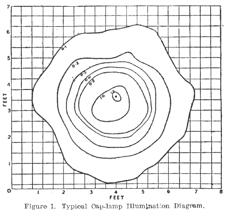
Examination of a representative illumination contour diagram for the present type of cap-lamp, showing illuminations of 0.1 ft.-c. upwards, when placed at a distance of 2½ ft. from the illuminated surface (FIGURE 1) shows that over an area of 26.5 sq. ft. the illumination varies from 0.1 to 1.5 ft.-c., the average illumination over this area being 0.28 ft.-c. As a result of this great variation the workman is in many cases unconsciously directing the maximum illumination or beam (in the above case an area 12 to 15 in. in diameter) on the work being done, and the problems which we set ourselves to solve, therefore, were (a) to redistribute the luminous flux in such a way that there would be much less variation in illumination over the working area and (b) to do this with the smallest possible loss of original flux.
The U.S.A. and British Requirements.
In the United States, where cap-lamps are almost universally used, a definite standard of distribution is laid down by the Bureau of Mines. The regulations relating to this are — (1) Total angle of light flux from the headpiece to be not less than 130°. (2) Average minimum c.p. delivered at any point in the illuminated area (taken at design voltage of bulb) shall not be less than 1 c.p. (3) The maximum c.p. at any point in the light stream must not be greater than five times the average over the light stream. (4) There shall be no sharp contrasts over the light stream.
The Lighting Regulations in this country read as follows :—
(a) Intensity of Light. — The lamp after burning continuously for nine hours under the appropriate standard conditions must give light such that the mean spherical candle-power (M.S.C.P.) is not less than 0.4, and the mean intensity over the horizontal angle of distribution (M.H.C.P.) must not be less than 1.5 candle-power.
(b) Distribution of Light. — The lamp must be so designed as to yield, throughout a continuous burning period of nine hours, a sufficient and suitable distribution of light, without giving rise to glare and as far as practicable without marked contrast of light and shade within the area of distribution. The lamp will normally not be regarded as having a suitable distribution of light unless the intensity of light is not less than one candle-power anywhere within a solid angle of 100°.
Thus the regulations in force in the U.S.A. (see (3) above) appear to make more definite provision against high lights on the working area than the Mines Department Regulations, although clause (b) given above covers this point to some extent but leaves the decision to the Testing Officer. The angle of the light stream is also greater — 130° as against 100° — but it may be noted that the much larger area thereby illuminated is not of great practical importance, as the maximum solid angle over which clear vision is possible with one position of the head is between 90° and 100°.
Trend of Experiments.
Before proceeding with the problem of the redistribution of the light flux, it was necessary to make a careful examination both of the total light output and the intensity distribution from the shape of the cap-lamp reflector in common use at the present day with various combinations of surface and bulb. . . . It was obvious that drastic alteration in the shape or size of the reflector, or of both, was necessary.
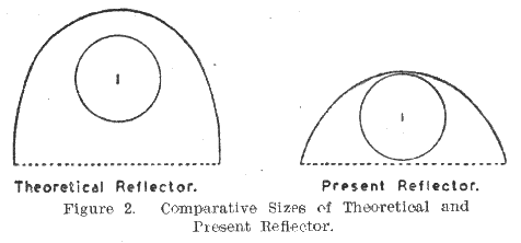
The profile of a reflector designed theoretically to give the uniform illumination aimed at, when used in conjunction with a line filament bulb — the filament lying along the reflector axis — together with the profile of a typical present-day reflector, are shown in FIGURE 2. Apart from the greater loss of luminous flux occasioned by the use of the larger reflecting surface, it will be realised that the fitting for a reflector of these dimensions, made of such material as would stand up to pit usage, was out of the question.
Because of these limitations of size and weight, we felt that it would be inadvisable to depart far from the present size of head-piece, and accordingly it was decided to endeavour to obtain the desired result by re-designing the profile of the existing reflector. It was also decided to adhere to the matt aluminium surface which in a previous investigation proved the best diffuser, and which also possesses the great advantage that it can be cleaned easily and quickly when it becomes tarnished.
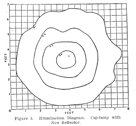
Having reached a stage approaching practical application, we succeeded in obtaining several reflectors of the desired shape, with slightly varied aluminium surfaces, from a firm of lamp manufacturers, and the illumination diagram for the best of these is shown in FIGURE 3 (lamp 2½ ft. from the illuminated surface). On comparing this diagram with that given by the present type of reflector (FIGURE 1), it will be found that the area illuminated to the 0.1-ft.-c. standard is 35.5 sq. ft. for the new reflector, as against 26.5 sq. ft. for the present type, and the areas illuminated to 0.2 ft.-c. (twice the minimum standard recommended) are approximately equal (see Table I.).
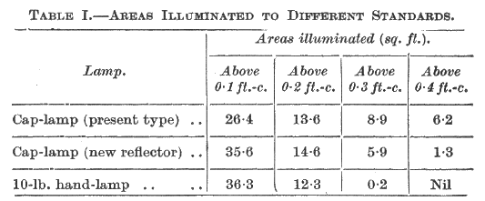
A comparison of the areas illuminated to different standards by the two cap-lamps is given in Table I., from which it will be seen that in the case of the cap-lamp with this new profile of reflector, at least the same standard of illumination over the same area of surface has been obtained and with a lamp of little more, and in several cases less, than half the weight.
This new reflector showed a great advance in the light distribution given by the cap-lamp, in that the variation in illumination had been reduced from 15 : 1 to 4 : 1, but it was still necessary to ensure that the system of double reflections which it involved did not result in too great a loss of total flux. Mean S.C.P. tests were therefore made with the new reflector and the present type, using the same headpiece and the same bulb at controlled voltage throughout, and it was found that the loss resulting from the use of the new form of reflector was approximately 9.5 per cent. We suggest, however, that the advantages obtained from the more uniform illumination will far outweigh such loss in total flux, and especially as the areas over which high illuminations are obtained are small when using the present type of reflector, while the variation in illumination over those areas is large.
The investigations along the lines of this Paper are, of course, by no means complete, and the loss of flux may be reduced as a result of further experimental work on different profiles and surfaces, which is in progress. The dimensions of the reflector described are : Diameter at front, 6.0 cm. ; diameter at back, 4.6 cm.; maximum depth, 3.7 cm.; depth in centre, 2.7 cm.
 |
 |
| Names mentioned in this article | |
 |
 |
| Name | Age | Occupation | Notes |
|---|---|---|---|
| Haldane, John Scott, Dr. | Whos Who Page | ||
| Holmes, S. | |||
| Llewellyn, T. Lister, Dr. | |||
| McMillan, William Hutchinson, Prof. | Whos Who Page |




 Contains public sector information licensed under the

