


| Newspaper Articles |

|
Newspaper Articles |
 |
 |
27th July 1929, Page: 10, Column: 1
Surveying Instruments
By J. L. Atkinson.
[At the ordinary general meeting in March of the Chemical Metallurgical and Mining Society of South Africa a paper on "The Latest Developments in British Surveying Instruments" was read by Mr. J. L. Atkinson, some twenty-four views of instruments being shown, as reproduced in the journal of the Society. Summary of paper appended with five of the illustrations.]
The first of the views showed an early theodolite probably dating back to the early 17th century, which was held by a ring at the top when observations were taken, fixed sights being provided for the determination of the angle. The circle was 10" in diameter, graduated to degrees quadrantal, that is from 0° — 90°. A special toggle joint was provided in the ring so that the circle hung perpendicular and provision was made for a horizontal position. Among the instruments of historical interest to which reference was made, were the Ramsden theodolite, the Cradle and Everest theodolites, and Fergusson's percentage theodolite, the Author remarking that although in the last 200 years many types of instruments have been made to suit varying conditions, the fundamental principles have remained unaltered.
All instruments to-day are fully protected against dust and water as far as it is mechanically possible tcdo so, and even where verniers are provided these are protected by glass covers, while foot-screws have been covered to a certain extent. Time saving being a very important feature nowadays, most designs incorporate special features to reduce the time taken on a given job, and this is very marked in present-day levels, as, in many designs, all readings are taken from the eye-end.
In the case of the modern level, one does not take time to set the axis of the instrument up truly vertical by means of the foot-screws provided, it only being necessary to adjust the stance of the level approximately vertical and then bring the bubble level for each sight by means of the gradienter screw, and even where a number of sights are to be taken from one station it is quicker to employ the quick setting device.
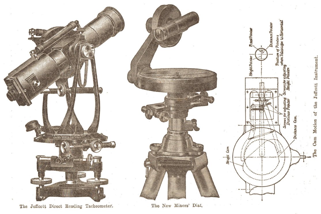
Another instrument which can be safely designated a time saver is the Jeffcott direct reading tacheometer, designed by Professor Jeffcott, late of the Dublin University, and now Secretary of the Institution of Civil Engineers, London. In ordinary tacheometry the greater portion of the time spent in producing the plotting data is in the reduction of the survey books after the field work has been done, and this the Jeffcott instrument eliminates entirely. By a system of cams mounted on the side of the telescope and fully protected from outside influences, levers are operated which vary the stadia intercept giving direct measurements of the horizontal, distances and vertical heights. All that the surveyor has to do is to read the three pointers provided in the diaphragm and by simple subtraction and subsequent shifting of the decimal points one or two places, his reductions are made and he has no office work to do at all except the plotting. The only complication arises when the fixed pointer is not brought to bear on the measured height ot the instrument, and this only slightly alters the simple calculation. If the centre fixed pointer is brought to bear on the instrument height, the calculation is ten times F minus L ; F denoting the fixed pointer and L the left movable pointer, while one hundred times R minus F gives the horizontal distance, R denoting the right movable pointer. From this it will be seen that all that is necessary is the shifting of the decimal points, and when one realises that over a hundred shots an hour can be taken with this instrument at an average accuracy of about 1 in 400, its value to engineers who have to get through a big tacheometer survey in a limited time will at once be realised.
The magnetic compass has received considerable attention, and most types are enclosed, the needle being read axially, either by an eyepiece or a disc and glass diaphragm, while the position on the instrument has been arranged for easier reading.
Another instrument is the improved miners' dial. This instrument is equipped with the usual clamps and slow motion screws, found on theodolites, and has a small telescope and vertical circle. The telescope is unique as it has no magnification, but it removes one serious difficulty in sighting with a dial, i.e., the bringing of three objects, at different distances from the eye, into one plane. Sights can be taken from either end of this telescope without any focussing at all, and as the whole of the top part of the instrument can be tilted over 60 degrees, sights truly vertical can be taken. Coupled with an all-metal telescope or broomstick tripod, the whole instrument makes a very compact and efficient surveying instrument for narrow workings.
At the moment there are two types of double reading theodolites on the market, both of which employ slightly different methods of dividing the circles ; one has the divisions on the top of the circle, while the other uses the edge. By dividing the circles on the flat of the disc, a complication will at once be apparent, for, as the divisions are radiating from a fixed centre, the individual division lines cannot be parallel to one another and, therefore, a special micrometer has to be employed. One point of considerable importance is the loss of light in transmitting the illumination through so many prisms and from reflecting surfaces, and the agelong ideas of such losses have been given a severe set-back. In order that the readings can be brought from the two circles, one standard of the instrument must be hollow to accommodate the necessary prisms and optical micrometer. Owing to the high magnification of the reading device, the circles can be reduced in size considerably, and we find two or three-inch circles being employed ; this naturally helps to reduce the overall dimensions of the whole instrument, and incidentally its weight, but here we are brought back to the original arguments for and against lighter instruments. A light theodolite is a decided advantage in certain circumstances, but whether they can remain rigid under severe conditions as did their predecessors is a very debatable point.
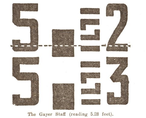
The Gayer Staff departs from the old pattern in many respects, and as it appears the right way up in the ordinary inverting telescope it has caused a considerable amount of consternation in various quarters. Normally, the staff stands on its head, as it were, but after one has got accustomed to this idea the reading becomes almost child's play. No matter at what point the staff is read, the foot, decimal point and first decimal place is always in view in plain figures, and when the diaphragm line cuts any .05 division the figure 5 forms itself. One advantage the Gayer staff has is that its division faces fold-over to protect one another as in the old stadia rod types, and being made of solid wood they come to no harm when inserted in water.
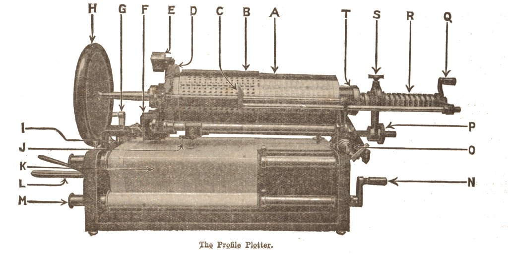
Turning to instrumental aids to office work, the Holland and Collingwood profile plotter is used for plotting sections or profile from direct information taken from the field books. A cylindrical drum forms the upper portion ; this actually consists of a long drum and a sliding sleeve. The drum itself is divided spirally to correspond to different altitudes, while the sleeve is a replica of the levelling staff divisions. By setting the zero of the sleeve at a number on the drum, corresponding to the line of collimation of the level when readings were taken in the field, the plotter is brought into adjustment, while in the case of soundings the water level is taken as the line of collimation. The hand wheel on the left is provided for rotating the drum together with the sleeve, and when this is rotated to bring the first intermediate sight under the index in the front of the machine the lever below the hand-wheel is depressed, thus transferring the first intermediate sight or sounding to the sectional paper stretched over the table. The transfer is made by a steel needle and the reduced level is printed in plain figures alongside the perforation. The sectional paper is now moved forward a distance, equal in scale to the distance of the next intermediate sight as recorded in the field book, and the process repeated so long as sights remain to be recorded, and the result is a sheet of sectional paper printed and perforated to correspond to the profile of the survey, and it is only necessary to join up these points to get a visible record of the work. Not only can the ordinary level be recorded, but it is possible to show the reverse ones as well and from them the amounts to be excavated or dredged as the case may be. Not only does the plotter do its work without calculation, but it cuts out a very fruitful source of trouble, i.e., individual mistakes in the normal reductions of book levels to a common datum ; at the same time it produces legible work in a fraction of the time taken by ordinary methods.
 |
 |
| Names mentioned in this article | |
 |
 |
| Name | Age | Occupation | Notes |
|---|---|---|---|
| Atkinson, J. L. | |||
| Jeffcott, —, Prof. |




 Contains public sector information licensed under the

