


| Newspaper Articles |

|
Newspaper Articles |
 |
 |
19th November 1927, Page: 134, Column: 1
Winding Engine, Accumulators, And Supermisers
There was a good attendance of members of the Past and Present Mining Students' Association at the November meeting, held in the Wigan Mining and Technical College, when Mr. Henry Pilling, M.I.Mech.E., gave a lantern lecture on "The Novel Steam Plant at Parsonage Pit, Leigh." The lecture in part followed the lines of a paper read in February, 1926, before the Manchester Geological and Mining Society. The Parsonage Pit, which is owned by the Wigan Coal and Iron Co., Ltd., includes for its power and winding plant: one direct-acting steam winding engine for No. 1 shaft, winding 645 yards in 48 seconds = 650 shaft horse-power ; one direct-acting steam winding engine for No. 2 shaft, winding 1,000 yards in 62 seconds = 790 shaft horse-power ; one direct-acting steam fan-engine, 600,000 cubic feet per minute, at 7 inches water-gauge = 660 air horse-power; one steam turbo mixed-pressure air compressor, 12,000 cubic feet per minute at 100 pounds = 2,000 air horse-power; two turbo mixed-pressure generators (one being spare) for general electrical purposes, each 1,500 kilowatts ; three steam accumulators for receiving the exhaust steam from the winders, the fan-engine, and the stand-by vertical steam air compressor ; twelve Lancashire boilers at 150 pounds pressure, with stokers, coal-conveyors, superheaters, and economisers.
The winding engine for the No. 1 shaft (built by Messrs. Galloways, Ltd.), is of the horizontal type with Galloway-Pilling drop-piston valves for the steam inlet, and double-ported piston valves with a quick acting motion for the exhaust. The total time of wind as stated is 48 seconds; total load 20 tons 7 cwt. ; boiler pressure 150 pounds gauge and minimum 120 pounds gauge; superheat 200° Fahr. The engines exhaust against a back-pressure not exceeding 6 pounds above atmosphere. In case of emergency the engines will have to wind men from a depth of 1,000 yards. Each cylinder is steam-jacketed and arranged for the distribution of steam by means of the Galloway equilibrium drop-piston valves, with separate valves for steam and exhaust, the admission-valves being on the top of the cylinders and the exhaust-valves on the underside. The valves derive their motion from constant-stroke eccentrics fixed on a steel lay-shaft carried in self-oiling bearings. The arrangement of the two lay-shafts is such as to allow properly for expansion and contraction of the engines due to changes of temperature, the shafts being so arranged as to preserve alignment under the varying conditions of temperature and load, and to prevent the eccentrics at the cylinder end or the wheels on the lay-shaft and at the crank-shaft end being disturbed in their alignment.
Each of the drop-valves is fitted with special duplex packing rings constructed so as to prevent the rings from falling into the ports even if fracture should occur. The reversing of the engines is effected by an oil-bath gear-box with steel wheels and machine-cut teeth fitted on each lay-shaft. The reversing-shaft is actuated by a powerful steam-cylinder fitted with oil-cataract cylinder. Each gear-box contains a nest of three machine-cut steel bevel-wheels running in an oil-bath. One wheel is firmly keyed to the lay-shaft, and another to the eccentric shaft, the two wheels being coupled together by means of the third wheel, which is mounted on a fixed pin carried in an oil-tight gear-case, capable of movement through an angle of approximately 60 degrees. It is this movement which gives the necessary angular displacement to the eccentric shaft, and with this gear the stroke of the valve is not altered but remains constant throughout reversal. The speed-control apparatus of the engine includes a powerful Whitmore governor equipped with the latest form of excess speed and over-winding devices. There is a separate and completely independent main governor connected to the drop-valve trip-gear, and so arranged that with the governors in action the cut-off of the engines will vary from zero to about 0.33 of the stroke, and with the governor in the bottom position the cut-off will be about 0.8 of the stroke, to facilitate the manipulation and starting of the engines. Immediately the acceleration period is over, the trips come into action, thus securing economical running. The connections of the main governor of the trip gear are arranged with a suitable detaching device so constructed that in the event of the engines being reversed whilst running at full speed the movement of the reversing-shaft disconnects the governor-rod, throws the cut-off gear to the late cut-off position, and thus enables full steam to be used against the engine in case of emergency. After the disconnection, the engines automatically reconnect the gear as soon as the governor falls to the lowest position.
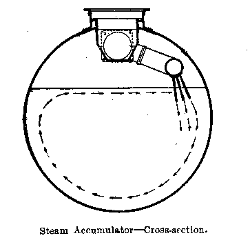
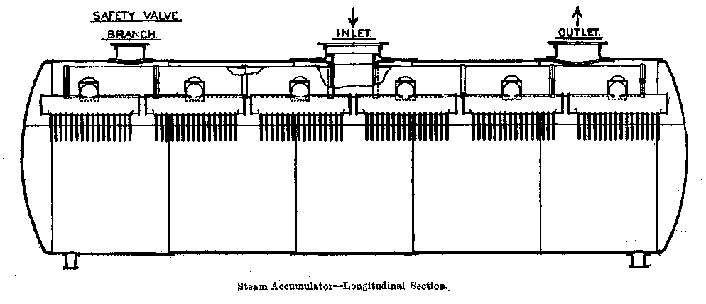
In his remarks on the accumulators the lecturer mentioned that there are three vessels in the scheme, each being 30 feet long and 9 feet in diameter. The combined water capacity is 243,000 pounds. The maximum amount of intermittent exhaust-steam to be stored is at the rate of 1,350 pounds in 30 seconds, thus the temperature rise in the accumulator will be 5.4° Fahr. The minimum pressure at the accumulator is usually about 1 pound per square inch above the atmosphere and the maximum about 3 pounds, with an occasional rise to 4 pounds. Careful observations of the water temperatures in the accumulators show that the difference of temperature between the top and bottom water is exceedingly small, being only about 1° Fahr. Such accumulators are in effect condensers, with the contained water as the condensing medium. The object of the design is primarily to set the whole mass of water into swift circular motion, with the moving water rushing past the steam-inlets in such manner as to give the greatest area of condensation contact. In the actual design the inlet-steam is admitted to a longitudinal distributing-pipe fixed along one side of the vessel well out of centre. From the pipe hang three rows of small-bore pipes, out of which the steam rushes with great velocity. The pipes are 1 inch in bore, and there are 400 in each vessel. Calculations showed, that the jet energy of the steam was amply sufficient to set even standing water into swift motion, and these expectations have been realised.
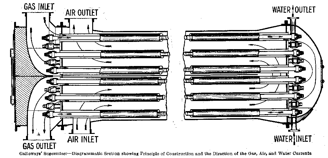
The members present showed very keen interest in the description of Galloway's supermiser, designed for the purpose of abstracting the maximum possible quantity of heat from hot flue gases before they are finally allowed to pass up the chimney. The supermiser (Leek's patents), which is compact and does not require any brickwork, consists essentially of a horizontal steel shell containing a large number of straight tube elements. Each element consists of an inner and outer tube, both of steel. The feed water is passed through the inner tubes, the air for supplying the boiler furnaces impinges on the outer tubes, and the hot gases pass through the annular spaces between the inner and outer tubes. The hot gases thus give up their heat, partly inwards to the water and partly outwards to the air. The air and gases are made to travel at a high speed through the apparatus, to obtain maximum rate of heat transmission, and to prevent deposition of soot and dust on the heating surfaces. The hot gases leaving the boiler flues are drawn through the heater by means of an induced draught fan, and delivered at the main flue leading to the chimney. The air for combustion is delivered to the heater by a forced draught fan, and thence through an air duct under slight pressure to the boiler furnace, which must be closed. It is claimed that the supermiser is exempt from air leakage ; that by reason of its supply of preheated air it improves the capacity and efficiency of boilers and enables cheaper fuel to be used, while at the same time the boiler is fed as usual with hot feed water ; that by its use the temperature of the hot flue gases can with consistency be reduced to a very low figure, usually about 250° Fahr., the net result being that the overall efficiency of the plant can usually be raised to at least 80 per cent.
On the Saturday (12th November) following the delivery of the lecture by Mr. Pilling, members of the Association visited the Parsonage Pit to view the plant.
 |
 |
| Names mentioned in this article | |
 |
 |
| Name | Age | Occupation | Notes |
|---|---|---|---|
| Pilling, Henry |




 Contains public sector information licensed under the

