


 |

|

|

|
|
 |
 |
|||
| Mine & Quarry Engineering | April, 1953 |
The problem in beneficiation
The specific gravity differential between fluorspar (3.2), calcite (2.71) and silica (2.65) is not large. Therefore, any method of gravity separation can only be satisfactory if the feed is close-sized or close-classified. Even so, it will be appreciated that the operation is very delicate.
Another factor to be considered, and pointed out by Pearson in a paper to the I.M.M, in 19466, is that because fluorspar is very friable large quantities of fines are produced, rich in spar. Gravity concentration is no use in up-grading these. (An instance of the extreme friability, of Weardale ore is given by Wood in the discussion of Pearson's paper "samples of lump spar, from 7 to 1 in. in size, when broken to ½ in. by careful stage-crushing, always produced 3035 per cent, of fines through 1/8 in. Moreover the fines were always richer in fluorspar than the coarse sizes".)
For a high-grade product it seems as if flotation is the only solution. But flotation has its difficulties, among them that Oleic acid, the most common collector for fluorspar, does not readily disperse in water at temperatures below about 25 deg. C. so a warm pulp circuit is needed. Heating of the pulp is a costly procedure, to be avoided if other means can be found to produce the desired effect.
According to Michell9 decrepitation has been tried as a means of up-grading at Rock Candy Mill, B.C. This treatment is based on the fact that fluorspar decrepitates on heating to 1200 deg. C. If the "calcine" is screened, silica reports in the oversize fraction so giving a degree of beneficiation.
In the United States, table agglomeration has been used while sink-float separations followed by flotation are popular10.
In this country, the only sink-float plant for fluorspar treatment known to the author is at the Glebe Mine, Derbyshire. This mine also has a flotation section. Another flotation plant is operated by Anglo Austral Mines Ltd., Nenthead, Cumberland.
It should be noted that a flotation concentrate is not of use to the steel maker because of the fine size. What he requires is a gravel-sized material which can be flung on to the surface of the molten bath in the furnace and which will not be carried out of the furnace in the gas stream. Many experiments have been carried out to try to briquette the flotation concentrates. Though on an experimental scale results were satisfactory, no method has yet met with commercial success in Great Britain, so far as the author is aware.
Treatment plant at Stanhopeburn
The present treatment plant uses a combination of gravity methods and flotation for recovery of fluorspar and the small amount of galena (about 2 per cent.) in the ore. In 1946 a gravity plant was erected to produce a jig concentrate of metallurgical-grade spar and a table concentrate of galena. The flotation plant was added at the beginning of 1950 to make acid-grade spar from the minus 1/8 in. material too fine for jigging.
Plant water with a head of 50-60 feet is obtained from a tank situated on the hillside above the gravity plant. This tank is kept filled automatically with water pumped from the burn. A supply of drinking water is piped from a spring high on the fellside behind the mine.
(I) Gravity plant
Ore is brought from the mine by battery locomotive. The loaded tubs are then hauled by winch, three at a time, up an incline so that they may be run on to a grizzly over the primary ore storage bin. The grizzly passes 4 in. material : any larger pieces are broken by a Broadbent jaw crusher set at 1½ in. The crusher product joins the grizzly undersize in the ore bin.
A reciprocating feeder draws the minus 4 in. ore from the bin at 5 tons per hour and delivers it to a 50-ft. bucket elevator feeding a 1 in. washing screen.
Until a few months ago screen oversize was passed to a circular picking table to allow the sorting of high-grade spar and also elimination of barren quartz lumps. This table is not now in use, all oversize passing to a second jaw crusher, set at about ¾ in. Output from this crusher, together with the screen undersize product, goes to a set of crushing rolls.
The material, now all minus ¾ in., is raised by a bucket elevator to a bank of four sizing screens. Reference to the flowsheet should make the circuit clear.
Oversize from the first screen (7/16 in.) falls back to the rolls for further crushing. The other three screens have apertures of 5/16, 3/16, and 1/8 in. respectively, producing the feeds for three banks of five-compartment Harz jigs. Part of the undersize material from the last screen forms the feed for four Holman sand tables, the surplus going to a storage dam.
The first compartments of the jigs yield galena-spar middlings which are crushed by another set of rolls and returned to the sizing system. The second, third and fourth jig compartments give spar concentrates while the last compartments give spar-silicacalcite middlings.
The jig stroke is short in the first compartments in order to make a clean hutch product and is longer in the last compartments to try to recover as much spar as possible. Lead slag is used as jig bedding material ; although not so heavy as galena it is much more durable.
Dreissen cones raise the density of the minus 1/8 in. pulp fed to the tables. An interesting feature is the provision of small thickening cones which are used to augment the Dreissens when their brass water jets become worn, so prolonging the life of these fittings.
The four tables are employed solely to produce a clean galena concentrate ; any lead which reports with the spar-silica-calcite tails is not lost as this material forms the feed for the flotation section.
(II) Flotation plant
The raw material for the flotation plant consists, then, of table sands, both drawn from current gravity operations and from stockpiles. The assay varies a good deal but averages around 70 per cent. CaF2 and 28 per cent. SiO2.
Material is ground to 95 per cent. minus 60-mesh in a 6 ft. x 3 ft. Denver high-discharge cylindrical ball mill working in closed circuit with an Akins-type 24 in. spiral classifier. The feed passes first into the classifier to reduce overgrinding and increase throughput.
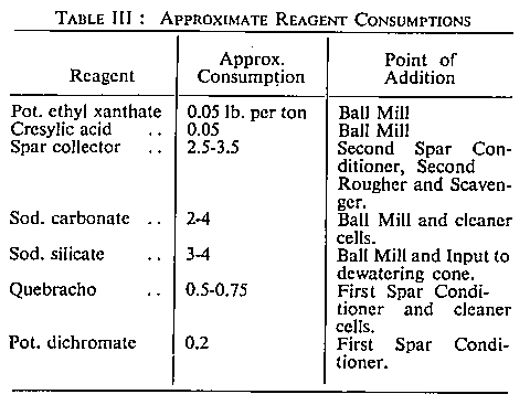
The following reagents are added to the ball mill feed to allow thorough conditioning: potassium ethyl xanthate to act as collector for lead minerals; cresylic acid as frother; soda carb. to raise the pH value; and sodium silicate to depress silica and disperse slimes
Because of its friable nature, fluorspar tends to concentrate in the fine fractions, as already mentioned, leaving silica in the larger sizes. Calcite slimes easily and much can be removed by a desliming operation.
The classifier overflow, at a pulp density of 32-35 per cent, solids, is pumped over to the buildings housing the flotation section by a 2 in. sand pump. Here the pulp first passes through two Denver No. 15 cells arranged as lead rougher and scavenger respectively. Rougher concentrate is treated in a cleaner cell while scavenger tails are pumped to a dewatering and desliming cone which brings the pulp density up to 40-45 per cent. solids, at the same time eliminating a substantial amount of calcite. More sodium silicate, to aid dispersion of slimes, is added before the pulp enters the cone.
The cone overflow goes to waste whilst the underflow passes to two conditioners in series, where the spar collector is added along with quebracho to depress calcite and potassium dichromate to depress any lead minerals still remaining in circuit. This dichromate also helps to depress calcite.
The fluorspar flotation circuit consists of two roughers, one scavenger and five stages of cleaner cells. All eight are Denver No. 15. Another scavenger would be advantageous11, for the tails still carry a quantity of fluorspar, but there is danger of bringing up silica if recovery is pushed too hard. In the cleaner section, sodium carbonate and quebracho are added to improve selectivity. Best results are achieved with the pH value kept around 8.5.
In an operation such as this, where the great bulk of material is being floated, the froth forms a relatively tight mat or blanket on the pulp surface in the cells. To give selectivity a froth system of a suitable nature is required and pulp should be pulled off rapidly. In many plants double-sided cells are employed.
Watersprays break down froth in the concentrate launders leading from one cell to the next.
Reagent consumptions are summarised in the following table :—
The final concentrate from the fifth cleaner cell flows by gravity to a 4-ft. diameter disc filter working under about 20 in. of vacuum. Considerable difficulty is experienced with the filter for the cloths blind and clog very quickly. Several different types of cloth have been tried but, at the time of writing, experiments have not been concluded.
Filter cake, containing 11-14 per cent. moisture, falls from the filter disc to a screw conveyor feeding directly into a 30 ft. x 3 ft. cylindrical drier. This rotary drier is fired by fuel oil and reduces the moisture content of concentrates to 0.25 per cent. or less. The drier can be driven at four different speeds, the slowest being 2 r.p.m.
A small bucket elevator lifts dried fluorspar from the drier outlet to a storage hopper beneath which is an Avery bagging machine. By this means the spar is packed into 1-cwt. paper bags ready for shipment by lorry.
Each 1-cwt. bag is sampled, individual samples being combined to give a bulk sample which is sent for assay once every shift. Normally the analysis is for CaF2, SiO2 and moisture. A typical analysis would be: CaF2 98.7 per cent.; SiO2 0.5 per cent.; moisture 0.2 per cent. The CaF2 determinations are made within one working day.
Labour
Altogether, Stanhopeburn mine employs between 100 and 120 men. Most of the underground work is done during day shift but some special operations such as shaft sinking are worked on a 2- or 3-shift basis.
The gravity concentrating plant runs for 9¼ hours a day, five days a week. This arrangement allows plenty of time for maintenance work and repairs to be carried out.
On the other hand, the flotation section runs continuously, being operated by four 9-hour shifts. This system of four shifts seems preferable in many ways to the three-shift system more usually encountered. It means that every fourth week each man gets a long weekend off; from Friday afternoon till the following Wednesday night, when he starts night shift for a week. In addition, the unfortunate and often-recurring round of twelve-hour shifts at the weekend, found with the three-shift system, is obviated.
Costs are not much greater with this four-shift arrangement since each man does not work so much overtime as would be the case with only three shifts. Admittedly the advantages of this scheme would not be so great in a country where the Mining Company had to sustain the cost of housing its employees. But at the same time the management gains by having on the job operators who have had a reasonable amount of free time between shifts.
The 9-hour shifts come about by the afternoon shift starting at 1.15 p.m. and the day shift finishing at 4.15 p.m. In this overlap period day shift does all the odd jobs around the plant, including mixing twenty-four hours' supply of reagents. This avoids the need for any permanent day shift labour being attached to the flotation plant.
Many of the employees live in villages several miles away from the mine. The firm provides good transport facilities for carrying them to and from work.
Acknowledgment
The author would like to express his gratitude to Fluorspar Ltd., for allowing him to publish details of their Stanhopeburn treatment plant in this article.
REFERENCES
- 1. Gregory, E., Metallurgy, 1932.
- 2. Dunham, Dr. K. C., Fluorspar, 4th edition H.M.S.O., 1952.
- 3. Wynne, I. Norman, "The Stanhope Burn Fluorite Mine," Mining Mag., November, 1943.
- 4. Davis, H. W., in Minerals Yearbook, 1949.
- 5. Lambeth, A. J., "Separation of Quartz and Fluorspar," Chem. Eng. and Min. Review, August 10th, 1950.
- 6. Pearson, A., "A Projected Central Mill for the Durham Fluorspar Industry," Trans. Inst. Min. Met., Vol. 55, 1946.
- 7. Rose, W. C. C., In Discussion on Pearson (see 6).
- 8. Clark, G., Prehistoric England, 3rd edition, 1944.
- 9. Michell, F. B., "Fluorspar," MINE AND QUARRY ENG., June, 1942.
- 10. St. Pierre, P. D. S., "General Notes on the Treatment of Fluorite Ore in the Rosiclare District, Illinois, U.S.A." R.S.M. Mining and Met. Soc. Journal, 1949.
- 11. Wrobel, Dr. S. A., Private communication.
Drawings and Photographs accompanying the article


Article reproduced from a copy of the magazine held at National Mining Museum Scotland, Newtongrange, Midlothian.




 Contains public sector information licensed under the

