


 |

|

|

|
|
 |
 |
|||

September, 1954
Koepe-winder Installation
A number of large Koepe winders were ordered by the National Coal Board for its post-war electrification schemes, and the first to be ready for service is a 3,720-h.p. installation at No. 2 shaft, Bradford Colliery, Manchester. This equipment was supplied and installed by Metropolitan-Vickers Electrical Co. Ltd. as main contractors, the mechanical portions being manufactured by Fraser and Chalmers Engineering Works, and the gears by David Brown & Sons, Ltd.
The new winder is designed for winding from an ultimate depth of 3,822 ft., which will be reached in three stages, each stage having a life of about 30 years. Two skips, each of 12 tons capacity, and for the first stage a locked-coil rope, will be used. The main technical particulars are given in Table 1.
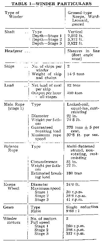
The ultimate stages will not come into operation for a number of years, and the size of rope to be used for these greater depths has not yet been decided upon. The winder was designed on the basis of a 2 7/8.-in. multi-strand rope of approximately 84 lb. to the fathom, but a locked-coil alternative may eventually be used.
As seen in the accompanying illustration, which was taken just before the rope was fitted, the motors are coupled to the pinions by Bibbytype flexible couplings. The main spur-gear wheel is on the same shaft as the Koepe wheel, and the whole is mounted on three pedestal bearings. The wheel tread material is elmwood, which when used in conjunction with a locked-coil rope appears to have extremely good resistance against wear; this is borne out by experience of such a combination at the Emma Colliery of the Dutch State Mines. The brakes are of the anchored-post type controlled by an M-V spring-brake mechanism. The brake engine and control gear are located in the basement beneath the winding engine.
The driver's control cabin is situated on a platform in line with the Koepe wheel and contains a driver's desk and trip-indicating panel. On the winder house floor are mounted the Ward-Leonard control panel, the signal relay cabinet (which is by the Automatic Telephone & Electric Co. Ltd.), and the M-V mine hoist recorder.
To assist in rope installation and changing, a 300-h.p. winch is provided, having a single plain cylindrical drum driven by an a.c. slipring induction motor. This winch is in the headgear structure and is controlled from an adjacent driver's platform. The switchgear and liquid controller for the winch are located outside the airlock in a room next to the winder room, the entrance to which can be seen in the photograph.
The winder motors are supplied from a motor-generator set situated in the power house, which is a separate building housing three turbo-compressor sets, the motor-generator sets for Nos. 1 and 2 winders, and the colliery substation; the whole of this equipment was supplied by Metropolitan-Vickers. The m.g. set for the winder under consideration consists of a 3,070-h.p. 750-r.p.m. 6.6-kV synchronous induction motor directly coupled to two generators, which are electrically interleaved with the winder motors, the d.c. voltage of the system being 660 on r.m.s. loading. The synchronous induction motor has VAX control of power-factor and is excited by a 26.4-kW 43-5-V overhung generator. The Ward-Leonard exciter is a 23 3-kW 220-V. machine and is overhung at the opposite end of the m.g. set.
The winder motors have the following rating :—
3,720 h.p. — continuous r.m.s.
6,000 h.p. — normal working peak.
8,600 h.p. — peak torque for rope-changing duty.
The electrical control scheme is on the standard open-loop system. In total, twelve one-square-inch section cables are installed between the motor generator house and the winders, i.e., three cables per leg of the connection.
The installation described in this article is the first Koepe winder to he installed in Great Britain since 1927, and is the biggest so far completed for a British coal mine. We are happy to acknowledge permission kindly given on behalf of the N.C.B. by Mr. E. W. Lane, General Manager of No. 1 (Manchester) Area, North Western Division, for the publication of these particulars.
Drawings and Photographs accompanying the article


Article reproduced from a copy of the magazine held at National Mining Museum Scotland, Newtongrange, Midlothian.




 Contains public sector information licensed under the

