


 |

|

|

| |
 |
 |
|||

August, 1952
Trolley locomotive installation at Beckermet mine
Drawings and Photographs accompanying the article
| Sample | Description |
|---|---|
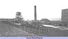 | Beckermet mine |
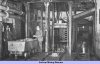 | Fig. 1 — No. 1 shaft bottom |
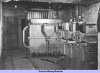 | Fig. 2 — Inside the transformer and rectifier station on the trolley locomotive system |
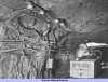 | Fig. 3 — A section point consisting of two dumbell-type section insulators with a switched neutral runner between |
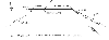 | Fig. 4 — Diagrammatic layout of the trolley-locomotive system at Beckermet |
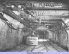 | Fig. 5 — The north end of the trolley-locomotive system near the shaft bottom, showing the double road for the marshalling area |
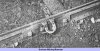 | Fig. 6 — A welded-type rail bond at a track joint |
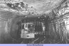 | Fig. 7 — The south (inbye) end of the trolley system, showing the crossover equipment with spring-back trail frogs and porcelain insulated supports |
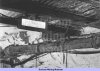 | Fig. 8 — The trolley-line termination and the illuminated danger notice at the north end of the trolley-locomotive system |
 | Fig. 9 — Diagram of electrical connections for the safety pull wire |
Article reproduced from a copy of the magazine held at National Mining Museum Scotland, Newtongrange, Midlothian.




 Contains public sector information licensed under the

