


 |

|

|

| |
 |
 |
|||

January, 1952
The South-West Durham pumping scheme
Drawings and Photographs accompanying the article
| Sample | Description |
|---|---|
 | Fig. 1 — Plan of the South-West Durham region showing the chief collieries and the areas waterlogged and dewatered |
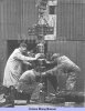 | Fig. 2 — Lowering the first Harland submersible pump |
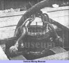 | Fig. 3 — The clamp used during the lowering of the rising main |
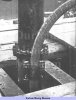 | Fig. 4 — The cable is entwined around the rising main |
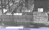 | Fig. 5 — The delivery pipe discharging into the rectangular-notch measuring box from where the water flows down a concrete culvert to the river Gaunless |
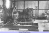 | Fig. 6 — The engineroom showing in the foreground the Pikrose winch for handling materials in the pumping shaft, and (towards the rear) the Tinsley winder operating the inspection cage |
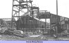 | Fig. 7 — General view of the pit top at West Auckland dewatering pit |
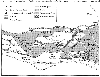 | Fig. 1 — Plan of the South-West Durham region showing the chief collieries and the areas waterlogged and dewatered |
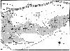 | Fig. 1 — Plan of the South-West Durham region showing the chief collieries and the areas waterlogged and dewatered |
Article reproduced from a copy of the magazine held at National Mining Museum Scotland, Newtongrange, Midlothian.




 Contains public sector information licensed under the

