


 |

|

|

| |
 |
 |
|||

March, 1951
Lynemouth Colliery
Drawings and Photographs accompanying the article
| Sample | Description |
|---|---|
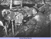 | Fig. 1 — A Mavor and Coulson arcshearer at work at one of the mechanised narrow-work faces |
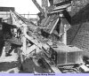 | Fig. 2 — Debris discharging from the chute on to the conveyor |
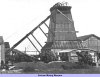 | Fig. 3 — A general view of No. 2 pit top during the shaft widening |
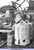 | Fig. 4 — The concrete mixers and drop-bottom kibbles at the top of No. 2 shaft |
 | Fig. 5 — The proposed pit bottom layout |
 | Fig. 6 — Showing the layout and the chief seams served by the horizon roadways |
 | Fig. 7 — The proposed arrangement of the standard loading station |
 | Fig. 8 — The drilling pattern adopted during the driving of the access drifts |
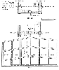 | Fig. 9 — Plan and sectional elevation of the proposed water standage |
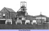 | Fig. 10 — A view of No. 1 pit top before reconstruction |
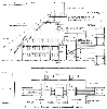 | Fig. 11 — Plan and longitudinal section of the proposed heapstead |
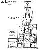 | Fig. 12 — End section of the proposed heapstead |
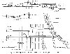 | Fig. 13 — Showing the proposed arrangement of surface conveyors and rail tracks |
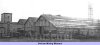 | Fig. 14 — The existing workshops and fan evasee at Lynemouth |
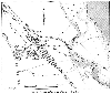 | Fig. 15 — Present surface layout of Lynemouth colliery |
 | Fig. 6 — Showing the layout and the chief seams served by the horizon roadways |
 | Fig. 6 — Showing the layout and the chief seams served by the horizon roadways |
Article reproduced from a copy of the magazine held at National Mining Museum Scotland, Newtongrange, Midlothian.




 Contains public sector information licensed under the

