


 |

|

|

| |
 |
 |
|||

January, 1951
Modernisation in North Northumberland
Drawings and Photographs accompanying the article
| Sample | Description |
|---|---|
 | Fig. 1 — Sketch plan of the region under consideration, showing the important collieries |
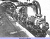 | Fig. 2 — The main pump room at Ellington colliery |
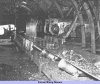 | Fig. 3 — A transfer point on the trunk conveying system at Ellington |
 | Fig. 4 — One of the main conveyor roads at Ellington |
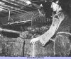 | Fig. 5 — One of the loading stations at Ellington |
 | Fig. 6 — The workings in the Diamond seam at Ellington colliery showing the proposed arrangement of haulage roads |
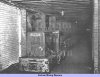 | Fig. 7 — The section of the arterial roadway supported by straight girders |
 | Fig. 8 — Details of the main arterial roadway, Ellington colliery |
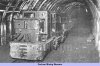 | Fig. 9 — A locomotive traversing the arched section of the arterial road at Ellington |
 | Fig. 10 — The Joy hydro-drill jib at work in the heading extension to the locomotive road |
 | Fig. 11 — The proposed layout of the reorganised pit bottom, Ellington colliery |
 | Fig. 12 — A Sullivan slusher working in one of the new pi-bottom drivages |
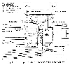 | Fig. 13 — The proposed surface arrangement at Ellington colliery |
Article reproduced from a copy of the magazine held at National Mining Museum Scotland, Newtongrange, Midlothian.




 Contains public sector information licensed under the

