


 |

|

|

|
|
 |
 |
|||

May, 1948
Huwood-Hudswell Diesel Mines Locomotives
The combination of Hudswell, Clarke & Co. Ltd. and Hugh Wood & Co. Ltd. represents an alliance between an old established firm of locomotive builders and a firm of mining specialists; a mining locomotive produced by such a combination may well be expected to be of exemplary design, containing only those features known to be best suited for the exacting conditions of colliery haulage. The Huwood-Hudswell was the first 100 h.p. flameproof diesel locomotive to be put into service, and the experience gained with this pioneer installation has led to a final design of proved suitability and performance. Hudswell, Clarke & Co. Ltd. are now building mines locomotives in 100 h.p. and 68 h.p. capacities, and we were recently privileged to visit their works to inspect examples of both sizes in running order.
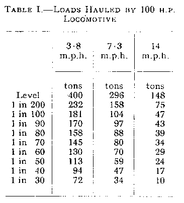
The larger locomotive is of the 0-6-0 type, can be built for gauges ranging from 1 ft. 11½ in. to 3 ft. 6 in., and can negotiate curves of 55 ft. radius. It has a wheelbase of 5 ft. 6 in., a length over buffer beams of 15 ft. 11 in., a height of 5 ft. 6 in., and a normal width of 5 ft. 0 in. In the case of the 1 ft. 11½ in. gauge the width can be reduced to 4 ft. It has three speeds in each direction, of 3.8, 7.3 and 14 m.p.h. respectively, at which tractive efforts of 8,300, 4,360 and 2,280 lb. are developed. The weight of the locomotive in running order is 15 tons. The gross loads that can be hauled (excluding the weight of the locomotive) are given in Table I, which is based on a starting resistance of 20 lb. per ton and a rolling resistance of 14 lb. per ton.
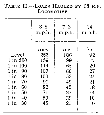
The 68 h.p. locomotive is a 0-4-0 machine having a wheelbase of 3 ft. 9 in. suitable for a minimum curve of 30 ft. radius. It is 14 ft. 5 in. long over buffer beams, S ft. 3 in. high, and 4 ft. 10 in. to 3 ft. 4 in. wide, the latter width applying to the 1 ft. 11 in. gauge. The speeds on the three gears are the same as those of the 100 h.p. locomotive, but the corresponding tractive efforts are 5,260, 2,740 and 1,430 lb., the locomotive weight being 10 tons. A table of gross loads corresponding to that already given for the 100 h.p. locomotive appears as Table II.
The two locomotives are similar in general design, and many of the details, such as transmission and brake components and radiator elements, are identical. This extends to the engines, which are four and six-cylinder versions, respectively, of an identical cylinder unit. The advantages of this degree of interchangeability between the two sizes of locomotive are obvious.
The power units are Gardner oil engines running at 1,700 r.p.m. The exhaust gas is cooled by a water spray in a cast Monel-metal exhaust pipe leading vertically down to the exhaust conditioner, which is mounted between the frame plates immediately behind the front buffer beam. In this conditioner the gas is compelled by a baffle box to pass through a water bath before it is able to emerge through duplicate flame traps situated on either side of the locomotive at wheel level-a position in which the exhaust cannot incommode the driver. Water for the spray is derived from a 14-gallon overhead tank, the spray being furnished by a belt-driven pump. A float in the overhead tank and a jockey pulley on the pump belt are connected with the fuel supply to stop the engine should the water supply become exhausted or the pump belt break. The water delivered by the spray is more than sufficient to compensate for evaporation of the water in the conditioner box, and the surplus overflows through the flame traps.
The flame traps are built up of stainless-steel strips mounted in a phosphor-bronze frame, but the usual form of strip with machined gaps is being superseded by a construction in which independent main strips and spacer strips are assembled into a pack and permanently welded. This not only reduces manufacturing cost by eliminating the milling operation on the plates but simplifies servicing, the pack being cleaned by plunging it in a degreasing bath and subsequently blowing it out with compressed air. The inlet flame trap is similar to the exhaust traps except that the frame does not need to be in phosphor bronze.
One of the outstanding features of the locomotive is the transmission, which has been designed by Hydraulic Coupling & Engineering Co. Ltd., and is by means of a Vulcan-Sinclair fluid coupling and a Sinclair S.S.S. (synchro-self-shifting) Powerflow gearbox. The Huwood-Hudswell was the first mines locomotive to be fitted with this transmission, this being a logical outcome of the experience of Hudswell, Clarke & Co. Ltd., who claim to have been the first to apply the fluid coupling to railway diesel locomotives.
The fluid coupling as used in this underground locomotive is shown in section in Fig. 2, and consists essentially of an impeller a, driven by the input shaft, and a runner b mounted on the output shaft. Impeller and runner are identical and are so shaped that together they form an annular working circuit in which oil is allowed to circulate. When the impeller rotates it acts as a centrifugal oil pump feeding oil to the runner, which acts as a turbine. The oil itself forms into a vortex ring circulating between impeller and runner, receiving kinetic energy from the impeller and transmitting it to the runner. Reserve oil is held in the reservoir casing c and is continuously fed to the working circuit by a scoop tube d, returning to the reservoir casing through leak-off nozzles (not shown). The scoop tube can be lifted out of the oil by means of an outside control, in which event the working circuit gradually empties and the coupling disengages.
The fluid coupling as described so far is by now a familiar mechanism, but the traction-type coupling as used on the Huwood-Hudswell locomotive and as illustrated herewith contains several points of interest. One of these is the provision for the rapid disengagement of the coupling when the engine is brought down to idling speed. Quick-emptying valves, shown at e in Fig 2 and seen in the foreground in Fig. 6, are fitted between the working circuit and the reservoir casing. At all working speeds these valves are held shut by centrifugal force, but at idling speed they open under the influence of their springs and rapidly drain the working circuit, with the result that disengagement is almost immediate.
At idling speed with the quick-emptying valves open but with the scoop tube in position there is a residual drag on the output shaft. This is so slight that it can be arrested by holding the output coupling flange with the thumb and finger, but it provides that degree of drift which enables gears to be engaged sweetly and with certainty when the locomotive is at rest. By withdrawing the scoop tube by means of a special control, this residual drag disappears.
The foregoing phenomena can be followed by reference to the characteristic curves given in Fig. 4, which show, to the left of the pick-up line, the residual drag torque, and, to the right, the engine torque curve and the coupling slip curves at full and half load. At full load and speed the coupling slip is only 2½ per cent. — in other words the coupling efficiency is 97½ per cent. At lower engine speeds the slip is appreciable at full load, but decreases rapidly as the load is reduced. Thus at low locomotive speeds, if conditions are easy the coupling still remains efficient, but if conditions are difficult the driver will naturally change to a lower gear, in which event the engine speed will be high and the coupling will be operating at an efficient point of the speed range.
A further valuable characteristic of the fluid coupling is its capacity to transmit an additional tractive effort at the moment of starting the train. This is due to the flywheel effect of the engine, and accounts for an addition of 20 per cent. to the steady tractive effort in first gear. Tests carried out by the National Coal Board on a Huwood-Hudswell locomotive at Fryston colliery showed a momentary starting tractive effort of 4,900 lb. as against the specified figure of 4,000 lb.
The S.S.S. Powerflow gearbox gives a foolproof automatic gearchange at all working speeds merely by moving the gearlever. No manipulation of throttle or of a clutch pedal is required, and as the gearlever merely operates control devices and does not actually perform the duty of sliding the gears it is light to move. A unique feature of the gear is that the drive is maintained during an upward change, so that there is no slackening and subsequent snatching of the couplings.
The gearbox is of the layshaft type with constant-mesh gears and dogclutch engagement, but is unique in three respects: (1) the automatic means of sliding the dog-clutches, (2) the method of making the gearchange at the point of synchronism, and (3) the feature, already mentioned, of maintaining the drive during an upward change.
When power is transmitted through a pair of single-helical gears the helix of the teeth induces an endwise thrust tending to cause the wheels to slide axially out of engagement with each other. The direction of this thrust depends on the "hand" of the tooth helix and on the direction of the drive; if the drive overruns-i.e., if the driven wheel feeds power back to the driving wheel-the thrust is reversed and the wheels tend to slide in the opposite direction. It is this reaction that is used to change gear in the S.S.S. box. First and second gears are through pairs of single-helical pinions, the driving pinions, which can rotate independently of each other, being loosely nested on the layshaft and free to slide so that endwise movement in one direction engages the first-gear dog-clutch and in the other direction second-gear dogclutch. The normal driving reaction feeds the nest towards first gear whereas an overrunning reaction feeds it towards second gear. Third gear is a direct drive through a pneumatically operated friction clutch.
The sequence is as follows: when the gearlever is in "first" the normal driving reaction slides the gear pinions into engagement with the first-gear dogs, where they are locked in position. On moving the gearlever to "second" the driving pinions are unlocked and the pneumatic clutch is momentarily engaged. This performs two offices: First, it provides a direct power drive to the running wheels while the gearchange is being effected, and secondly it overruns the helical gears, reversing the end-thrust reaction and sliding the pinions over into engagement with the second-gear dogs. An abutment ring now comes into position to prevent the pinions sliding back towards first when the normal drive is restored, and the pneumatic clutch is disengaged, leaving the gears in "second." Third gear is brought into action merely by engaging the pneumatic clutch, in which event second gear is overrun and slides forward harmlessly to a disengaged position. Incidentally this ability to overrun second gear provides a valuable coasting feature; by engaging second gear and closing his throttle the driver can run freely on a down gradient with his engine idling. On changing down from "third" to "second" the pneumatic clutch is disengaged, allowing second gear to be brought back into engagement by the end-thrust reaction. Similarly, on changing down to "first," the abutment ring is moved so that the pinions are free to slide into first gear.
It now remains to describe how these gearchanges are compelled to take place at synchronism. When a gear is offered for engagement the sliding dog at first rotationally overruns the fixed dog, but it progressively slows down until a point of synchronism is reached; thereafter, failing engagement, the sliding dog would lag behind the fixed dog. It is therefore arranged that the sliding dog, on moving towards engagement, is first compelled to ride over a set of ratchets mounted on the fixed member. As long as the sliding dog is overrunning the fixed dog these ratchets are also overrun, but immediately synchronism is reached they engage the sliding-dog teeth and hold them in proper register for engagement; this action also locks engaging and engaged members together, upon which the end-thrust reaction slides the dogs positively into mesh.
A separate reverse gear is incorporated in the gearbox, final drive being by jackshaft and coupling rods. Coupling rods are fitted with gunmetal bushes and the wheel axles run in phosphor-bronze axleboxes. The locomotive frame is a riveted structure of open-hearth steel plate, each side being formed of a single plate extending from front to rear.
Westinghouse braking equipment, air-operated sanding gear, pneumophonic horn and flameproof electric lighting are included in the equipment.
Drawings and Photographs accompanying the article


Article reproduced from a copy of the magazine held at National Mining Museum Scotland, Newtongrange, Midlothian.




 Contains public sector information licensed under the

