


 |

|

|

| |
 |
 |
|||

December, 1941
A modern colliery winder (1)
Drawings and Photographs accompanying the article
| Sample | Description |
|---|---|
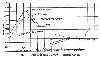 | Fig. 1 — Horsepower-time diagram of electric winder |
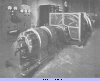 | Fig. 2 — Motor-generator set showing exciters in foreground. Incoming cubicles and d.c. auxiliary contactor and instrument panels are along the wall |
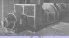 | Fig. 3 — Opposite end of the motor-generator set |
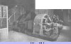 | Fig. 4 — The Metropolitan-Vickers 2,500/5,000 h.p. Ward-Leonard electric motor |
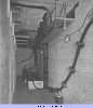 | Fig. 5 — View in basement showing oil switch and liquid starter for motor-generator set. The cable trays, slung from the ceiling, are a feature of the wiring |
 | Fig. 6 — Excitation circuit of the Metrovick "VAX" synchronous induction motor driving the motor-generator set |
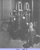 | Fig. 7 — Engines for compound brake |
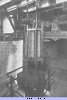 | Fig. 8 — Spring box and deadweight for compound brake |
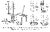 | Fig. 9 — Arrangement of Metrovick compound brake system, with diagrams showing sequence of operation |
Article reproduced from a copy of the magazine held at National Mining Museum Scotland, Newtongrange, Midlothian.




 Contains public sector information licensed under the

