


 |

|

|

|
|
 |
 |
|||

April, 1939
Electric Winder at Trimdon Grange Colliery
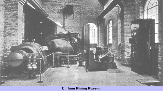
We were recently afforded an opportunity of inspecting a new electric winder installed by Metropolitan-Vickers Electrical Co. Ltd. at the Trimdon Grange pit of East Hetton Collieries Limited. The equipment is an example of up-to-date practice in electric winding, and is of particular interest in that it incorporates the new design of control desk which Metropolitan-Vickers have recently introduced.
The winder has been designed for a duty of 100 tons per hour from a depth of 900 ft., allowing for a decking time of 21 sec. This involves double decking, but there is a possibility that simultaneous decking may be adopted ultimately, in which case the capacity will be increased to 130 tons per hour, with an allowable decking time of 8 sec.
The mechanical parts of the winding engine were built by Robey & Co. Ltd. A grooved parallel drum 9 ft. in diameter is employed, running at a maximum rope speed of 346 ft. per sec. It is geared to the driving motor through single-reduction gearing, the motor being connected through a Wellman-Bibby coupling.
Curved suspended brakes are arranged on either side of the drum, and are actuated by an oil-operated brake engine. To supply this engine a weight-loaded oil accumulator is installed in the basement, fed by duplicate electrically driven oil pumps.
The winder motor is of the slipring induction type, rated at 650 h.p. at 570 r.p.m. Control is achieved by a contactor reversing panel, liquid controller and acceleration governor, all operated by a single lever on the control desk.
In view of the heavy switching duty involved in electric winder control, the reversing contactor is of a type similar to that developed for electric traction. It consists of two three-pole air-break circuit breakers, one for each direction of rotation, which are mechanically and electrically interlocked so that one cannot close unless the other is open. The contactors are operated by direct-current solenoids energised by a potential transformer and a Westinghouse metal rectifier.
Speed control is obtained by means of a liquid controller actuated by an acceleration governor. This governor is an oil-operated device which repeats the position of the driver's lever but moves the liquid-controller dippers at a predetermined controlled rate. It thus has a twofold function: it acts as a mechanical relay, enabling the driver's lever to be small and light to operate; and it accelerates the winder automatically, so that the driver's lever can be thrown immediately to the full-speed position. The electrolyte of the liquid controller is water cooled, the cooling water being circulated through a Heenan & Froude cooler.
Power for the winder is received from the colliery sub-station by duplicate feeders at 2,750 V, and is controlled by an oil circuit breaker of 50,000 kVA rupturing capacity.
A Lilly overwind preventer is fitted, and is of the two-governor type, the high-speed sensitive governor coming into action when winding men. Should the Lilly controller register an overspeed or overwind, it trips the main circuit breaker, shutting off power to the winder and also causing the brake to be applied. The arrangement of the brake rigging to provide for an immediate brake application when the power is shut off is very simple and avoids the necessity for a separate resetting lever. The driver's lever operates the brake engine valve through a floating link, the fulcrum of which is normally held up to its working position by a solenoid. If the power is shut off, the solenoid releases the fulcrum and allows it to fall under the influence of a weight. This has the effect of applying the brake without recourse to the driver's lever. Resetting is performed by moving the driver's brake lever to the on position; unless the lever is in this position the circuit breaker cannot be closed nor the solenoid energised.
A further protective device is a rotation relay. The Lilly controller has, of course, decelerating cams for each direction of rotation, and in default of provision to the contrary these cams would limit acceleration during the early part of the wind. The driver's starting lever is therefore connected into the Lilly-controller circuit in such a manner that for either direction of rotation the cams for the opposite direction are cut out during the accelerating period. A complication arises, however, in that reverse-current braking is employed. Reversal of the driver's lever for braking would, of course, cut out the wrong set of cams, and this is prevented by a rotation relay which adjusts the controller circuit according to the direction of rotation of the winder. It consists merely of a mercury switch tilted in one direction or the other by a brake band riding loosely on a small pulley driven by the winder.
A detailed view of the control desk is given in Fig. 2. It centralises all controls and indicators in a compact form conveniently to the driver, and as both the liquid controller and the brake engine are oil operated, the respective levers have been made small and can be handled with a minimum of effort. As will he seen from Fig. 1, it has been placed on the floor in such a position that the driver has a full view of the winder.
Reverting to Fig. 2, the brake and control levers are on the left and right respectively and the men-coal lever on the rear panel. On the right is a palm-operated emergency stop switch, and below is a pedal-operated backing-out switch for drawing out after an overwind. This pedal cannot be operated unless the brake lever is on and the control lever off, and permits a start only in the direction to draw out of bank.
In the centre of the rear panel is a depth indicator of a type developed for use with this desk. It consists of a cylindrical paper-covered drum which rotates once for each revolution of the winder drum. Two pointers travel up and down on either side of the drum and reproduce the movement of the cages, the cage travel per revolution of the winder drum being indicated by a series of equidistant rings inscribed round the indicator drum. Owing to the combination of drum and pointer movements, the path traced out by each pointer on the drum is helical, and the great length of path thus obtained enables the cage positions to be determined with a high degree of accuracy. Decking positions are marked in ink or pencil direct on the indicator drum; the driver can at any time place any special marks thereon, and these can be erased when they cease to he required. The drum is protected by a glass cover.
On either side of the depth indicator are start and stop push-buttons, with indicator lights, for the two oil-pump motors, and indicator lights for men and coal and for the main circuit-breaker position. Instruments include an ammeter, voltmeter, clock, and oil-pressure gauge.
In presenting this account we are pleased to acknowledge the courtesy of East Hetton Collieries Limited, and particularly of Mr. O. Carter, the chief engineer, in allowing us to inspect the equipment in operation.
Drawings and Photographs accompanying the article


Article reproduced from a copy of the magazine held at National Mining Museum Scotland, Newtongrange, Midlothian.




 Contains public sector information licensed under the

