


 |

|

|

|
|
 |
 |
|||

March, 1934
Colliery Re-Organisation on the North East Coast - I
The Cowpen Coal Co. Ltd. have adopted intensive coal mining methods, laid down new coal treatment plant and are now sinking a new pit
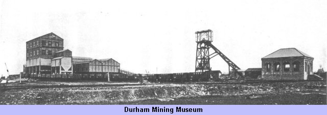
Bates pit screens and washery
The Cowpen Coal Co. Ltd. are operating a compact group of six pits in the neighbourhood of Blyth, about 18 miles north-east of Newcastle-upon-Tyne. A sketch map showing the disposition of the collieries in relation to the railway facilities and the river Blyth is reproduced in Fig. 1. In all, the royalty comprises about 15,000 acres, several thousands of which lie under the sea. The company was reconstructed in 1928 when an extensive reorganisation scheme was initiated, the work being carried out under the supervision of Mr. Sidney Bates, who was appointed director and mining engineer at this time. It is to Mr. Bates that we are indebted for facilities to visit the various Cowpen collieries, and we take this opportunity of acknowledging this and his several other kind offices on this occasion.
Briefly, the reorganisation has consisted of introducing intensive methods of machine mining underground — the old hand methods having given way to face conveyors, scraper loaders, gate-end loaders and gate conveyors — in effecting economies by the application of electricity to the haulage and winding equipment, and in remodelling the entire coal-preparation and loading plants in line with the best modern practice. In addition a new pit — the Bates pit — has been sunk in the immediate vicinity of the river Blyth to exploit a new area of coal, and this coal, as will be seen later, will be shipped direct into sea-going vessels with a minimum of handling charges. When working to capacity the new pit alone will contribute 2,500 tons per day to the output, and the better methods employed elsewhere have also greatly augmented the tonnages raised, the liberal use of coalcutters having particularly contributed towards this end. In 1933, that is, before the full effects of the electrification could be realised, the annual Output had been considerably increased; in this year it amounted to 1,200,000 tons, the whole of this coal being raised in single shift.
These changes may seem modest enough at first glance, but as all the pits are old — some of them exceedingly so, for instance, the "A" pit at Cowpen was sunk in 1782 — they have, in effect, been of a revolutionary order. Even the most recent of the older pits dates from 1885, and as very little attempt had been made to keep the equipment abreast of the times a ruthless policy of scrapping had to be followed.
Since the re-equipment work is thus too wide in scope for us to cover in its entirety in an article of this kind, we propose to describe more or less typical instances of what is being done. Beginning with the face operations, a fairly representative example is afforded by a double-unit face in the Plessey seam of the Cambois pit. Here the seam is 2 ft. 8 in. in thickness, and is cut at the bottom to a depth of 4 ft. 6 in. (4 in. high) by two Anderson Boyes machines, one being employed on each of the 70-yard single faces. A 20 in. wide Meco belt conveyor is in service at one side and a Blackett chain conveyor on the other, both these units discharging into a 26 in. Meco belt in the mothergate. As a variation of this arrangement, gate-end loaders — of Meco or Mayor & Coulson manufacture — are substituted for the gate conveyor. In this case ample width (12 to 15 ft.) is provided for the necessary double tubway instead of the 9 ft. gate which suffices for the conveyor. In either case the back gates are driven 8 ft. in width.
Where the conditions are suitable, a further variant lies in the use of scraper conveyors. Certain faces in the Yard seam of the Cambois pit are won in this way. The seam is 2 ft. 8 in. in thickness and a 4-ft. 6-in, cut at the floor level is again made by Anderson Boyes machines. Sullivan double-drum gears are used for the haulage of the skips along the face, and are provided with various sizes of motors, ranging from 20 to 30 h.p., according to the duty. The skips and loading bridges were manufactured in the Cowpen Company's central workshops, which are fully equipped to carry out work of this kind. In passing it may be mentioned that the pit tubs are also made at these shops, and consist of steel bodies mounted on oak frames; they have a capacity of 13 cwts. and a tare of 7 cwts., the wheels being 12 in. in diameter and mounted on open pedestal-type bearings.
Timber supports are at present universally used both for the roadways and on the faces, but recently some fairly extensive experiments have been initiated with steel supports in some of the new roadways in the Bates pit. In connection with the timber supports the favourable situation of the collieries to compete in the Scandinavian market is not without influence, as not only can the timber be handled with the same ease and cheapness as the coal is loaded, but the exchange is, of course, of mutual benefit in providing an equable basis of trade.
The intensive methods of mining were not adopted at the face without full consideration being given to the haulage arrangements. In the vicinity of the face the compressed-air haulages formerly used for auxiliary work have all been replaced by electrically driven machines of the "putter" type. Various makers have shared in the supplying of these — Mayor & Coulson, Austin Hopkinson, John Wood, and Tinsley. The main haulages were already electrified before the reorganisation commenced, and any new ones that have been installed are simply due to development work; at the Bates pit, for example, a new 150 h.p. haulage, by Tinsley & Co. of Darlington, has been installed.
Power plant and winding equipment
The total electrification of the power services has naturally involved the obsolescence of a large amount of steam and compressed-air plant. In all, 29 Lancashire boilers have been shut down, these having been variously employed at the different pits in supplying steam to the winders, compressors and ventilating fans. At North Seaton a 3,000 cu. ft. horizontal compressor has been scrapped, the same fate having also overtaken two units of similar capacity at the Cambois pit. The compressing plants at the Isabella and Mill pits — which had a total capacity of 10,000 cu. ft. per min., have also been discarded, together with the auxiliary pumps, cutting machines, &c., that they served. A certain number of hammer drills have been retained for drift work and holing whin dykes, and these are fed locally from Ingersoll Rand electrically driven compressors of 200 cu. ft. capacity. Otherwise the drilling required for coal and ordinary stone work is done by rotary drills, these having been supplied, complete with their gate-end gear, by Siemens-Schuckert (Great Britain) Limited and the Consolidated Pneumatic Tool Co. Ltd. Wimet tipped bits are used with this equipment. The pneumatic hammer drills used for the hard holing are of Hardypick manufacture.
The winding equipment has suffered a similar violent adjustment to modern needs. At North Seaton colliery the old single-cylinder steam-driven winder has been replaced by a 3-phase induction motor geared to a 10-ft. diameter parallel drum. This equipment has been erected on the opposite side of the shaft to the old winding house, and the old wooden headgear has been replaced by one of steel-girder construction. A view of the new winder is reproduced in Fig. 8; it was supplied by the English Electric Co. Ltd., the mechanical parts having been manufactured by Fullerton, Hodgart & Barclay Limited. The motor develops 365 h.p. (R.M.S.) at 418 r.p.m. and has been constructed on the double-frequency principle in order to retain the same speed when the periodicity of the supply in this area was changed from 40 to 50 cycles. Formerly it ran as a 14 pole machine on the 40 cycle supply, but when the frequency changeover took place last year the windings of the reconnected motor were altered to convert it into a 14-pole 50-cycle machine. The length of time which elapsed between placing the machine in the makers' hands and having it running as a 50 cycle motor was 32 hours — from 2 a.m. on the Saturday morning to 10 a.m. on the Sunday morning — so that no interruption to the working of the pit was necessitated. The gearing is of the double-helical single-reduction type with 14 in. width of face, having a ratio of 10.4 to 1, a Wellman-Bibby coupling being inserted between the motor and pinion to afford flexibility. An unlagged steel-barrel cylindrical drum is provided, 10 ft. in diameter and 5 ft. 9 in. wide. This carries a 45 in. circumference winding rope of the locked-coil type supplied by British Ropes Limited. With the full-load motor speed of 418 r.p.m. the maximum rope speed is 21 ft. per sec. The whole equipment has been designed to deal with an unbalanced load of 5,824 lb. according to the winding cycle reproduced in Fig. 10.
Oil-pressure post brakes are provided, the braking force being applied by heavy weights and held off by fluid pressure. The oil supply is drawn from a vertical deadweight-loaded accumulator which is fed by duplicate oil pumps driven by 1½ h.p. motors. The rotor regulator, which is of the liquid-resistance type, is fitted with the English Electric Company's accelerating device, enabling the wind to begin at any predetermined rate of acceleration. In this a small motor is arranged to drive the liquid controller, and is put in and out of action by a switch worked in conjunction with the main operating lever, it being possible to set the timing to any safe limit desired. The reversing switch is of the air-break contactor type, and is also operated from the master lever. Emergency breaking is provided for by a Lilly controller; this equipment, it will be recalled, not only guards against overwinds but also prevents overspeed during the full-speed period of the run, and initiates retardation at the proper instant towards the end of the run should the winding engineman neglect to do so. Further protection against overwinds is afforded by two limit switches, fitted on the depth indicator and actuated by travelling nuts at the limits of travel.
As a final safeguard, two backing-out switches are provided, so arranged that after an overwind it is impossible for the winding engineman to switch on in the wrong direction, thus ensuring that the overwound cage will be brought back to the proper decking level. These switches are so interlocked with the master switch of the controller that if by any chance the driver pressed the wrong backing-out switch he would be unable to energise either the forward or the reversing contactor; by pressing the correct switch either the forward or the reversing contactor only is energised, depending on which cage has been overwound.
Precisely similar winding equipment has been installed at the Cambois pit, as the accompanying schedule (Table I) shows. In this case the frequency change over was effected in 27 hours — from 11 a.m. on the Saturday, July 1, to 2 p.m. on Sunday, July 2. Double-decked cages are in use in both cases, but simultaneous decking has not been adopted.
| Table giving charactistics of new electric winders | ||
|---|---|---|
| North Seaton | Cambois | |
| Depth of shaft (ft.) | 757 | 659 |
| Circumference of rope (in.) | 4.5 | 4.5 |
| Ultimate drum spees (r.p.m.) | 40.4 | 40.4 |
| Motor speed (r.p.m.) | 418 | 418 |
| Gear ratio | 10.4:1 | 10.4:1 |
| Voltage | 625 | 625 |
| Weight of coal (lb.) | 5,824 | 5,824 |
| Weight of tubs (lb.) | 3,248 | 3,248 |
| Diameter of headgear sheaves (ft.) | 12 | 12 |
| Balance ropes | Yes | No |
| Brake heads | 10 ft. x 10 in. | 10 ft. x 10 in. |
| Arc of contact | 60° | 60° |
As a corollary to these changes the whole of the ventilation system has been thoroughly overhauled, the old type Waddle fans having been replaced by high-capacity Sirocco equipment. Thus, at North Seaton a 17 ft. Waddle fan has been scrapped to make place for a 105 in. diameter Sirocco unit, which is rope driven by a 280 h.p. Metrovick induction motor. Similarly, a 77 in. double-inlet Sirocco has been substituted for a steam driven 12 ft. diameter Waddle fan at Cowpen, and a 77 in. single-inlet Sirocco for a 40 ft. Waddle at the Mill pit. As a result of these changes, such is the improvement in the conditions, it has been possible to replace safety lamps with naked lights.
The new sinking
As already indicated, the site of the new Bates pit was chosen conveniently near the river with a view to loading the output direct into sea-going vessels, thus eliminating railway dues. The pit will exploit hitherto untouched areas of the High Main and Bensham seams, and will ultimately contribute some 2,500 tons of coal to the daily output in two shifts. It is 14 ft. in diameter and is lined with brick lumps, 9 in. in thickness, behind which a concrete backing has been inserted. Rigid guides are fitted, carried on buntons fixed into cast-iron boxes which were built into the walling as the shaft was lined.
The preliminary work in connection with the sinking was undertaken by the Cowpen Company themselves, the first sod being cut in April, 1932. This consisted of making the surface excavation down to the rock head, a depth of 13 ft., inserting the concrete foundations for the headgear, and erecting the headgear itself. The balanced doors and tipping platform for the debris were supplied by Ayres & Co., of Newcastle. A view of the headgear is given on page 95, this structure being of the steel girder type standing 56 ft. 3 in. in height to the pulley centres. Banking out will take place at ground level. The sinking proper was entrusted to Messrs. Joseph Denham, of Coundon, Co. Durham, who took over in August, 1932, the Bensham seam being reached at a depth of 750 ft. At the time of our visit the shaft inset was being excavated, a view of this work in progress being reproduced in Fig. 12. This work was also being done under contract by Messrs. Denham. To break the ground Hardypick hammer drills are in service, the air supply being derived from an old 1,000 cu. ft. compressor situated at the surface, a 600-volt 185 h.p. slipring induction motor providing the drive.
Drawings and Photographs accompanying the article


Article reproduced from a copy of the magazine held at National Mining Museum Scotland, Newtongrange, Midlothian.




 Contains public sector information licensed under the

