


 |

|

|

| |
 |
 |
|||

April, 1931
A Notable Low-Temperature Plant
Drawings and Photographs accompanying the article
| Sample | Description |
|---|---|
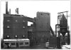 | Fig. 1 — General View of the Plant at Dunston, showing the Old and New Retort Houses |
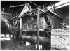 | Fig. 2 — The 60-Ton per Day Retort Unit, showing Combustion Chamber on the Right |
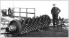 | Fig. 3 — An Extractor Roller and Star Wheel Casing |
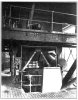 | Fig. 4 — Discharge End of Semi-Coke Quencher and Conveyor |
 | Fig. 5 — Diagrammatic Section of Retort |
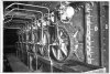 | Fig. 6 — Hydraulically Operated Coke Extractor Gear |
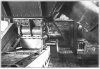 | Fig. 7 — Coke Discharge Valve from Retort to Conveyor and Quencher |
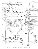 | Fig. 8 — Part Sectional Drawings of Rectangular Retort |
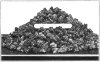 | Fig. 9 — Typical Semi-Coke Screened for Domestic Use |
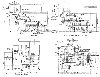 | Fig. 10 — Drawings of 60-Tons per Day Equipment as erected at Dunston |
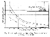 | Fig. 11 — Graph showing Operating Costs as Affected by Capacity of Plant |
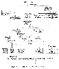 | Fig. 12 — Typical Coal Yield Diagram |
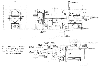 | Fig. 13 — Layout for Standard 75-Ton per Day Retort and Recovery Plant, Operating Independently |
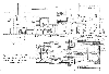 | Fig. 14 — Layout for Standard 300-Ton per Day Retort and Recovery Plant, Operating Independently |
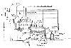 | Fig. 10 — Drawings of 60-Tons per Day Equipment as erected at Dunston |
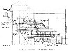 | Fig. 10 — Drawings of 60-Tons per Day Equipment as erected at Dunston |
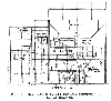 | Fig. 10 — Drawings of 60-Tons per Day Equipment as erected at Dunston |
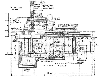 | Fig. 10 — Drawings of 60-Tons per Day Equipment as erected at Dunston |
Article reproduced from a copy of the magazine held at National Mining Museum Scotland, Newtongrange, Midlothian.




 Contains public sector information licensed under the

