


 |

|

|

|
|
 |
 |
|||

November, 1930
A Novel Colliery Ropeway
An Unusual Design of Ropeway, four miles long, connecting two pits owned by the Co-operative Wholesale Society Ltd., is described.
The economy of aerial ropeway transport has been brought before our readers by descriptions of several important installations which have been put to work during the last year or so. In common with most coal mining plant, however, ropeways for colliery work have each that uniqueness which results from the almost infinite variation of individual circumstances, so that in describing the present equipment we are in no way repeating ourselves but are showing how an entirely separate and specific problem has been solved.
The directors of South Shilbottle Collieries (1928) Ltd.* were confronted with the problem of bringing the output from their Longframlington pit to a central screening plant at Whittle Colliery, and after considering various modes of transport decided that a ropeway offered the cheapest and most efficient solution. This equipment, which was erected by Messrs. R. White & Sons, Widnes, Lancs., the well-known ropeway designers and manufacturers, has several unique features, and has now been tried out by several years of practical operation. It is constructed on the bi-cable principle and is about four miles in length, the capacity being 32 tons per hour. Perhaps the most important variation from normal practice is that instead of buckets being used, the pit tubs themselves are used to carry the coal; this being done to reduce breakage of the coal to the lowest possible amount. A special type of carrier was designed for this purpose and has since been patented by the makers. Various views of this are reproduced in the accompanying illustrations (Figs. 3 and 5); it has been so designed that either full or empty tubs can be run in entirely automatically by gravity from an inclined tramway. During the loading operation the carrier frame stands on a fixed shunt rail, and as soon as the pit tub enters, a stop is released and the carrier and tub run simultaneously by gravity towards the outgoing end of the terminal. Here the carrier, in which the tub is now automatically fixed, rises from the rails and is engaged automatically by the hauling rope to be taken along the ropeway in the usual manner. The tub carries a nett load of 6½ cwt. and is hauled along the cable rope at a speed of 330 ft. per min.
On entering the terminal station the carrier is similarly released in an automatic manner at the required point, the tub being run on to an inclined tramway, so as to be clear of the hanger supports and finally left free to run to its destination by gravity.
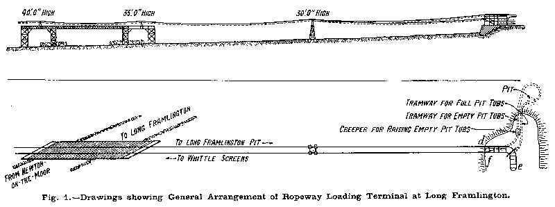
Drawings showing the general arrangement of the loading terminal at Longframlington are given in Fig. 1. The carrier with the empty tub enters the terminal at the point (d) and after being automatically released from the hauling rope runs along the fixed rail to a point at which the tub is stopped by a special gear. The carrier proceeds by gravity around the loop (e) to the forward side of the terminal, where it is stopped by a buffer gear in position to receive a loaded tub. Whilst running round the loop (e) the carrier releases the special stopping gear for the tub, referred to above, and the empty tub is then run by gravity on to a creeper, which takes it up to the banking level ready for going into the pit. The full tubs from the pit travel by gravity to the point (f) at the loading station, where they are automatically picked up by the carrier frames in the manner described.
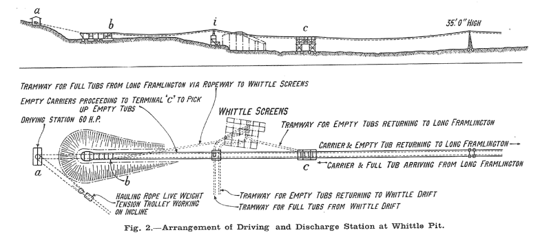
Fig. 2 shows the arrangement of the driving and discharge station at Whittle pit. Here the carriers with their loaded tubs enter the terminal at (b), the tub being set free and brought up by a spring buffer, in the tramway stop. The reaction causes the tub to reverse its direction and it then runs by gravity along an inclined tramway to the screening plant, where it is discharged at the required point. When emptied it runs by gravity along a further inclined tramway and rejoins the ropeway at (c).
The carrier makes the complete circuit of the return terminal without being disconnected from the hauling rope or without being stopped or handled in any way. It is, of course, drawn up at the point (c) where it receives an empty tub for the Longframlington pit.
From the foregoing it will be gathered that the whole handling of the pit tubs is as automatic as possible in order to reduce the attendance charges to a minimum. Only one man and two boys are thus required to work the ropeway, the man attending to the driving gear while one boy looks after the return of the empties at Whittle pit and the other sees the despatch of the loaded tubs at Longframlington. A motor of 60 B.H.P. provides the drive and is housed in a building at (a). The tensioning arrangements for the hauling rope are also situated at the terminal end and comprise a tension pulley mounted on a loaded trolley which runs on an incline. Fig. 10 shows the intermediate line tension station for the carrying cables. This has an entirely steel construction but, as the various views show, wood has been used for the intermediate supporting towers and parts of the terminals. The plant has given every satisfaction in operation, the arrangement for connecting and disconnecting the pit tubs having proved exceedingly effective over the several years the ropeway has now been in use.
* Now owned by the Co-operative Wholesale Society Ltd.
Drawings and Photographs accompanying the article


Article reproduced from a copy of the magazine held at National Mining Museum Scotland, Newtongrange, Midlothian.




 Contains public sector information licensed under the

