


 |

|

|

| |
 |
 |
|||

August, 1927
Ashington Colliery - II
Drawings and Photographs accompanying the article
| Sample | Description |
|---|---|
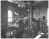 | Fig. 19 — View of Carl Pit Winder with Conical Drum |
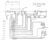 | Fig. 20 — Schematic Diagram for Electro-Pneumatic Decking Equipment |
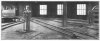 | Fig. 21 — View showing Valves for controlling the Skotch Blocks (on right of illustration) and for Opening the Points |
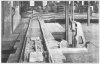 | Fig. 22 — Tipplers, Weighbridge and Retarder, showing Control Valve for latter on Wall of Weigh Cabin |
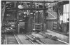 | Fig. 23 — View showing Ram Heads and Front and Rear Skotch Blocks at Pit Top |
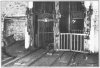 | Fig. 24 — Running-off Side of Pit Bottom, showing Gates and Controllers in Main Cage |
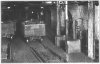 | Fig. 25 — Pit Bottom, Running-on Side, showing Retarders for Full Tubs |
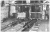 | Fig. 26 — A further View of the Running-on Side, showing Decking Rams, &c. |
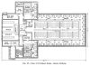 | Fig. 27 — Plan of Pit-Head Baths, Linton Colliery |
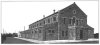 | Fig. 28 — Exterior View of the Ellington Baths |
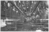 | Fig. 29 — Changing and Drying Room, Ellington Baths |
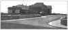 | Fig. 30 — Lynemouth Institute and Entertainment Hall, with Concrete Bridge over Railway in Foreground |
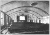 | Fig. 31 — Interior of Entertainment Hall |
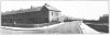 | Fig. 32 — Lynemouth, showing Five-Roomed (on left) and Three-Roomed Houses |
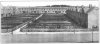 | Fig. 33 — Chester Square, Lynemouth, showing Three-Roomed Houses and Gardens |
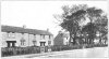 | Fig. 34 — Park Road, Lynemouth, giving View of Four-Roomed Houses |
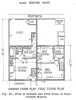 | Fig. 35 — Plan of Ground and First Floor of Four-roomed Houses |
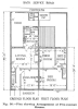 | Fig. 36 — Plan showing Arrangement of Five-roomed Houses |
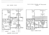 | Fig. 37 — Plans of the Six and Three-roomed Houses |
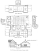 | Fig. 38 — Plans and Side Elevation of Institute and Hall |
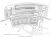 | Fig. 39 — Plan Lay-out of Lynemouth Village |
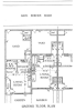 | Fig. 37 — Plans of the Six and Three-roomed Houses — Ground Floor Plan |
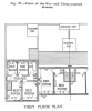 | Fig. 37 — Plans of the Six and Three-roomed Houses — First Floor Plan |
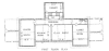 | Fig. 38 — Plans and Side Elevation of Institute and Hall — First Floor Plan |
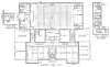 | Fig. 38 — Plans and Side Elevation of Institute and Hall — Ground Floor Plan |
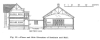 | Fig. 38 — Plans and Side Elevation of Institute and Hall — Side Elevation |
Article reproduced from a copy of the magazine held at National Mining Museum Scotland, Newtongrange, Midlothian.




 Contains public sector information licensed under the

