


 |

|

|

| |
 |
 |
|||

June, 1924
Silica Bricks and Wilputte Coke Ovens
Drawings and Photographs accompanying the article
| Sample | Description |
|---|---|
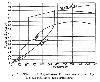 | Fig. 1 — Thermal Expansion Curves as shown by Le Chatêlier's Experiments |
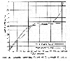 | Fig. 2 — Graphs showing Effect of Thorough Burning |
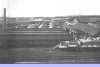 | Fig. 3 — General View of the Silica Brickworks, Templetown |
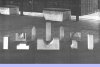 | Fig. 4 — Some Silica Shapes for Coke Ovens |
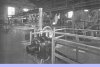 | Fig. 5 — General View of Crushing and Mixing Plant |
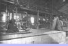 | Fig. 6 — The Chain Bucket Conveyor, Automatic Weighing Pans and Grinding Mills |
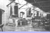 | Fig. 7 — The Moulding Benches |
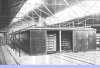 | Fig. 8 — "Proctor" Drying Machine, showing Rack Cars |
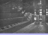 | Fig. 9 — The Wilputte Ovens during Course of Construction |
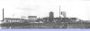 | Fig. 10 — General View of Fell Coke Ovens and By-product Plant |
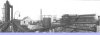 | Fig. 11 — Nearer View, showing Ovens and Gas Mains |
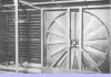 | Fig. 12 — Drying Machine Fan and Steam Coil |
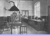 | Fig. 13 — Laboratory of Templetown Silica Brickworks |
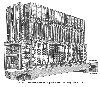 | Fig. 14 — Sectional View of Wilputte Ovens, showing Gas Circuit |
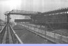 | Fig. 15 — The Pushing Ram |
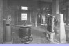 | Fig. 16 — A Portion of the Control Room |
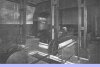 | Fig. 17 — Change-Over Gear |
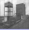 | Fig. 18 — Coke Car and Quenching Tower |
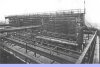 | Fig. 19 — Atmospheric Cooling Range |
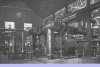 | Fig. 2 — The Exhauster House |
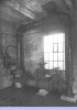 | Fig. 21 — Automatic Valve Gear for Quenching |
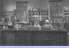 | Fig. 22 — Coke Works Chemical Laboratory |
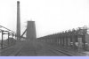 | Fig. 23 — View of Oven Tops, showing Bunker and Short Ascension Pipes |
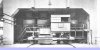 | Fig. 24 — Charging Car under Coal Bunker |
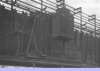 | Fig. 25 — Near View of Coke Guide |
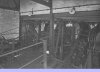 | Fig. 26 — Coke Screening Plant |
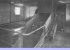 | Fig. 27 — Cascade Grizzley Screen |
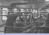 | Fig. 28 — Centrifugal Dryers for Sulphate |
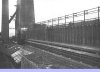 | Fig. 29 — Discharge Side of Ovens, showing Loading of Coke Car |
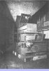 | Fig. 30 — Pennsylvania Crushing Machines, showing Concrete Hopper |
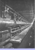 | Fig. 31 — Fuel Gas Main and Gas Valves |
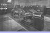 | Fig. 32 — Two 200-kw. English Electric Rotary Convertors supplying D.C. to the Plant |
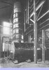 | Fig. 33 — Stills and Condensing Set |
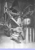 | Fig. 34 — Boilers burning Coke Breeze and Surplus Gas |
Article reproduced from a copy of the magazine held at National Mining Museum Scotland, Newtongrange, Midlothian.




 Contains public sector information licensed under the

