


Mail: Webmaster

|

|

|

|
|
Part I
THE FACE BELT CONVEYOR
Chapter I
GENERAL DESCRIPTION OF A FACE BELT CONVEYOR
 A Face Belt Conveyor is a machine for carrying the coal from the coal face. It loads the coal into tubs or on to a second conveyor and consists of the following main parts
| (a) |
The Engine End, sometimes called the drive head, gear-head or unit.
| |
| (b) |
The Belt.
| |
| (c) |
The Intermediate Structure to support the belt.
| |
| (d) |
The Tension End or Return Drum.
|
(a) The Engine End
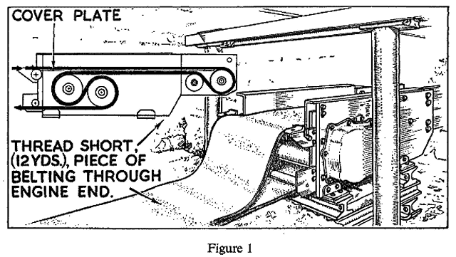
This consists of a metal framework containing the motor, the reduction gears and the belt driving rollers or drums (Figure 1).
The motor which drives the drums through a train of reduction gears will generally be between 10 and 20 h.p., and may be of compressed air or electric type.
(b) The Belt
Conveyor belting is made of layers, or plies, of woven cotton (called cotton duck) which have been impregnated with rubber. These layers are enclosed in a rubber cover. It is the cotton duck that enables the belt to withstand tension. The rubber protects the cotton from damage.
The belting is usually sent underground in lengths of about 25 yards. They are joined in various ways (see Part II of this Manual) when the belt is placed on the conveyor so that it becomes endless. The top and bottom portions are supported by rollers in the intermediate structure.
The belt is made to move by the friction or grip between itself and the surfaces of the driving drums. In order to obtain sufficient grip two driving drums are frequently employed, and the belt is threaded round them as shown in Figure 1 (inset).
(c) The Intermediate Structure
This is the framework between the engine end and the tension end. It is made of short sections (Figure 2) so that they can be moved between the props on the coalface fairly easily. Each section is of the same size and consists of a stool or standard, rollers, and various plates. One or two of the sections are constructed in such a way as to permit slight adjustments to be made in the length of the conveyor. They are called Telescopic sections and may be placed at the tension end and the engine end according to circumstances.
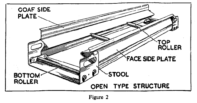
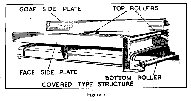
There are two main types of intermediate structure, one called the Open type (Figure 2), and the other called the Covered type (Figure 3). The covered type is used to prevent spillage from the top belt from falling on to the bottom belt.
(d) The Tension End
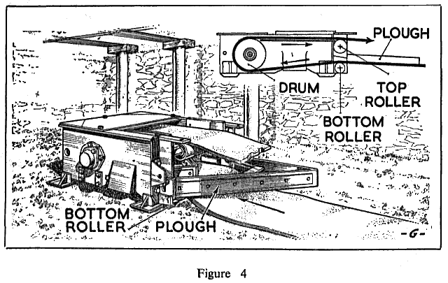
The Tension End consists of a box-like structure containing the return drum, round which the belt passes (Figure 4). A scraper device or plough is attached to it to prevent materials returning on the bottom belt from passing into the box and so fouling the return drum or damaging the belt.


Back |

Home |
Copyright © 1999-2012 by The Durham Mining Museum and its contributors
Page last updated: 01 Jan 2008 |

Search |

|